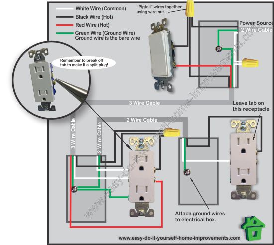
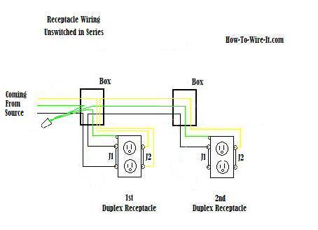
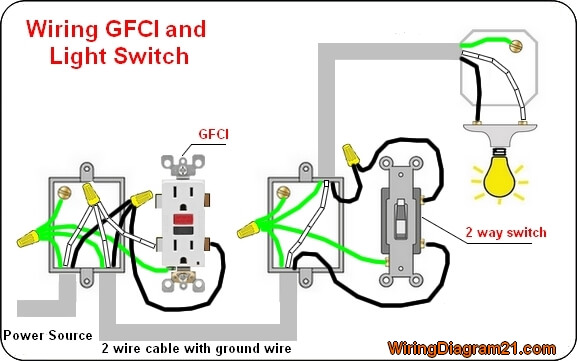
Here a receptacle outlet is controlled with a single pole switch. How to wire an electrical outlet wiring diagram wiring an electrical outlet receptacle is quite an easy jobif you are fixing more than one outlet the wiring can be done in parallel or in series.

Receptacle Wiring Diagram Wiring Diagram
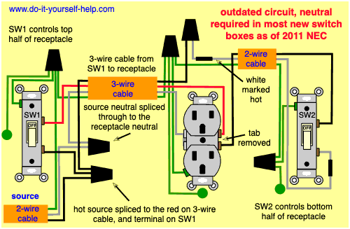
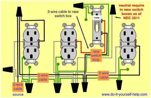
Receptacle with switch wiring diagram. The hot source wire is removed from the receptacle and spliced to the red wire running to the switch. Steps to take when wiring the electrical outletreceptacle. The source is at the outlet and a switch loop is added to a new switch. This wiring diagram illustrates adding wiring for a light switch to control an existing wall outlet. In this diagram 2 wire cable runs between sw1 and the outlet. Wiring a switch to a wall outlet.
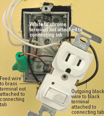
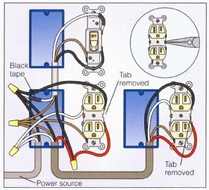
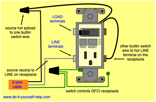
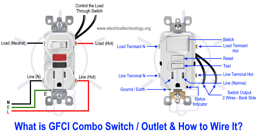
Wiring a gfci outlet with combo switch outlet receptacle light switch. The black wire from the switch connects to the hot on the receptacle. Wiring diagram of a switched electrical receptacle outlet and an unswitched electrical receptacle outlet with the power entering the switched outlet electrical box from the circuit breaker panel. This is commonly used to turn a table lamp on and off when entering a room. They can work in conjunction with one another or they can be connected and used independent of each other. The source is at sw1 and the hot wire is connected to one of the terminals there.
The single pole switch has a neutral conductor for future electronic controls such as a timer or a wifi switch. It means all the connected loads to the load terminals of gfci are protected. In this gfci outlet wiring and installation diagram the combo switch outlet spst single way switch and ordinary outlet is connected to the load side of gfci. The switchreceptacle combo device is set up like a duplex receptacle but has a 15a single pole switch in one half and a single 15a 125v receptacle in the other half.


