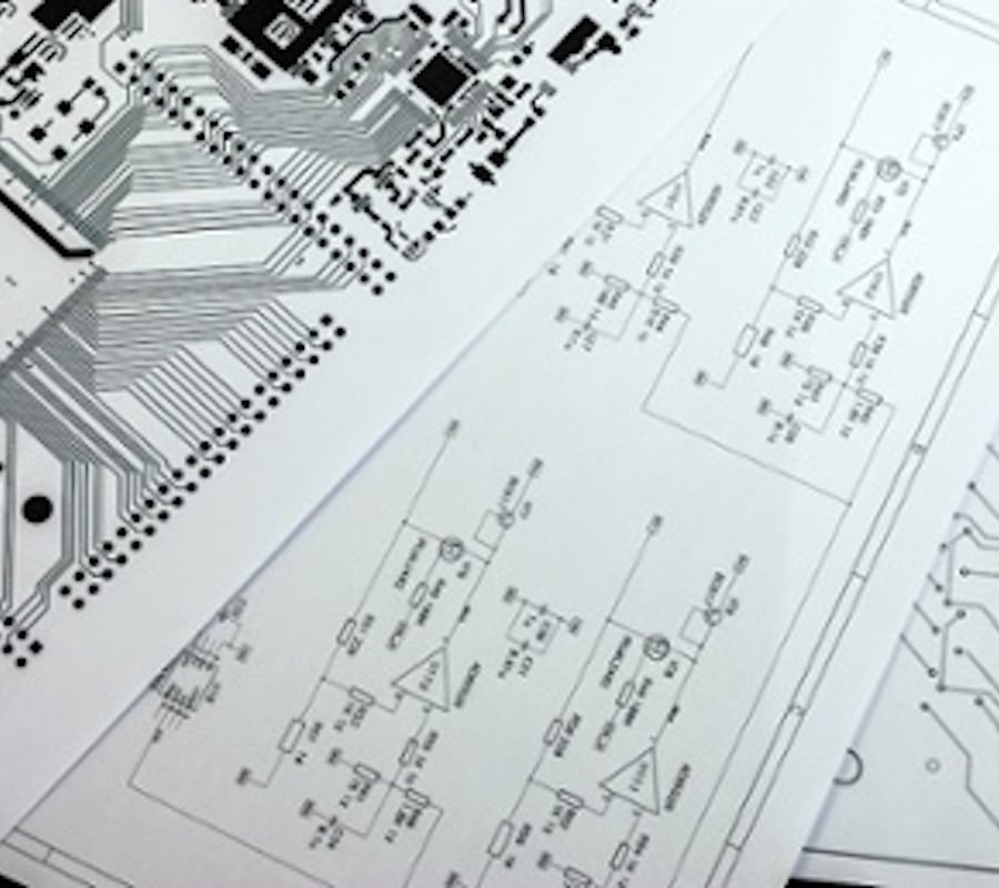
Another plc of the company allen bradley micrologixplc wiringsimilarly we have input terminals hereoutput terminals here. To store the program when there is.

How To Wire An Orenco S Series Control Panel
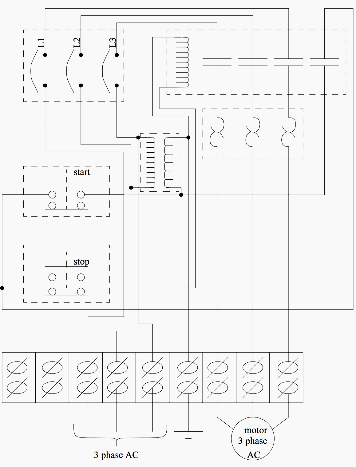
Plc panel wiring diagram. Figure 5 below shows a schematic diagram for a plc based motor control system similar to the previous motor control example. An industrial control cabinet with wire runs terminal strip buttons on plc panel front etc. Shows which direction power flows through the circuit. It shows the elements of the circuit as streamlined shapes as well as the power as well as signal connections in between the tools. Now this battery is used to store the information. The electrical design for each machine must include at least the following components.
In an industrial setting a plc is not simply plugged into a wall socket. In order to increase io points on plcs without increasing the number of connections commons are used. The picture to the right shows an example of what the wiring of a plc with 4 inputs would look like. Electrical wiring diagrams of a plc panel. When including a plc in the ladder diagram still remains. But it does tend to become more complex.
It is a 2 door control panel on the front of which we have some switches that are connected to the plc inputs and outputs. Assortment of plc panel wiring diagram pdf. As ive mentioned in the previous articles this is a control panel that is used for a system that turns wastewater into clean water. In case of power failure. Everything inside the dashed box happens inside the plc. Lets go back and have a look at the control panel and try and figure out some of the connections by following a wiring diagram.
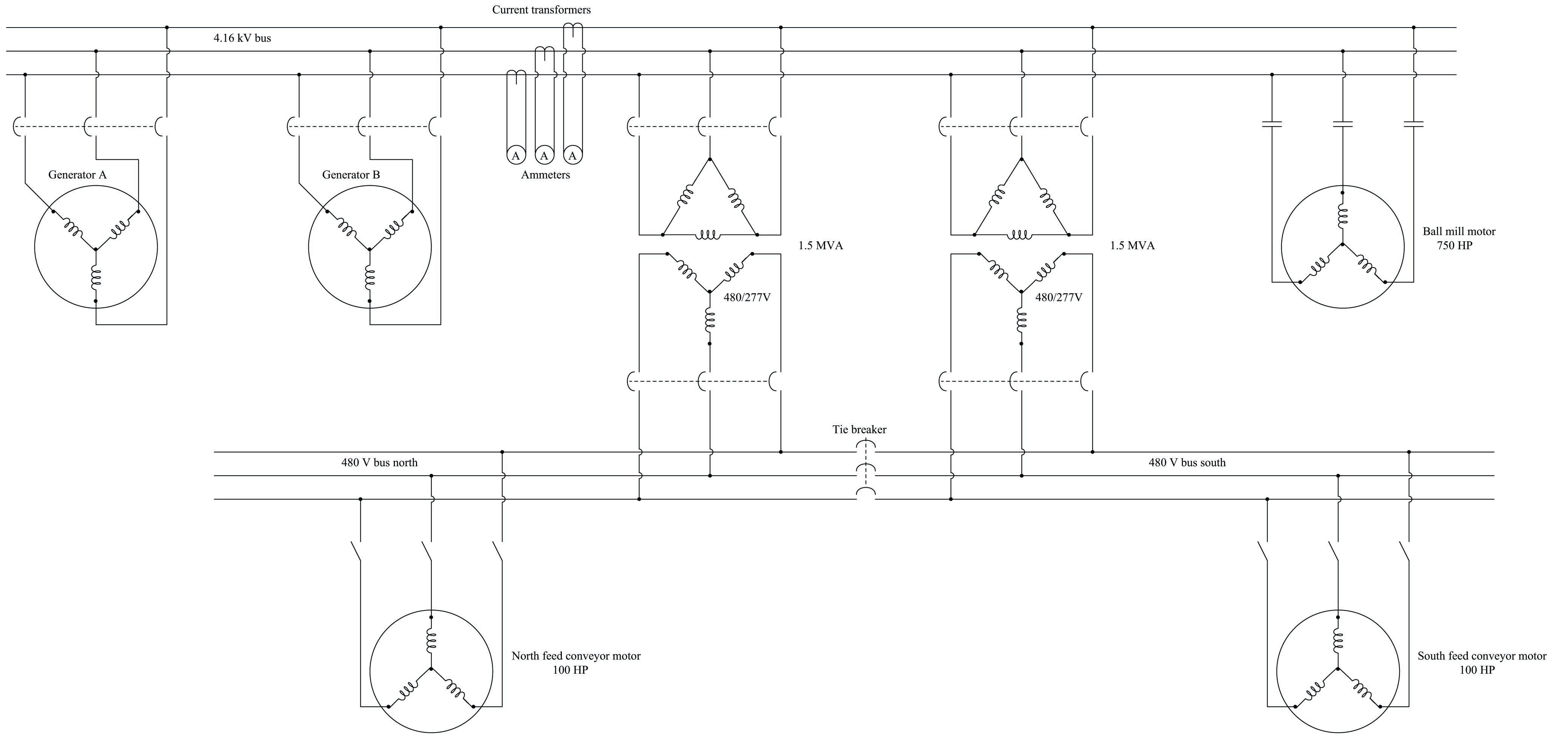
A wiring diagram is a simplified conventional photographic representation of an electric circuit. Transformers to step down ac supply voltages to lower levels. And again programming cable to program a plcthat is the battery.


