Street light sensor connection 10. Wiring diagram for cell best wiring diagram vw polo 6n archives.

How To Make A Remote On And Off Switch With A Contactor Latching Circuit
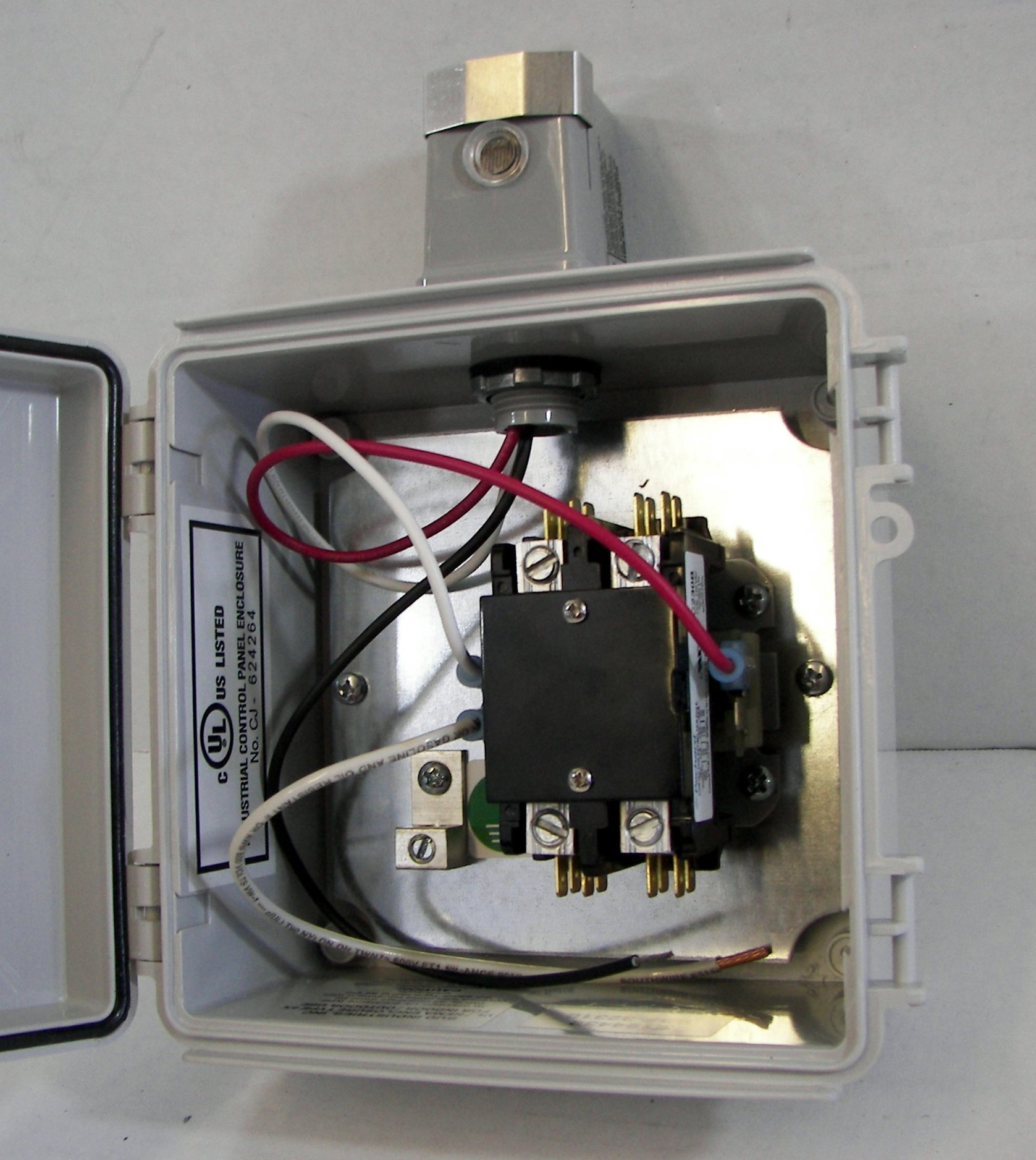
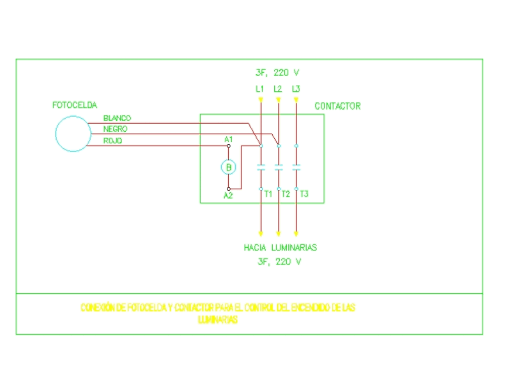
Photocell contactor diagram. Electric switch wiring diagram gallery. Each component ought to be set and linked to other parts in specific manner. Refer to the lighting control contactor wire diagram for the specific photocell voltage. Thus energy is saved by ensuring the lights are only on during hours of darkness. How to wire and connect a intermatic pool pump timer in wiring. Light sensor switch 9.
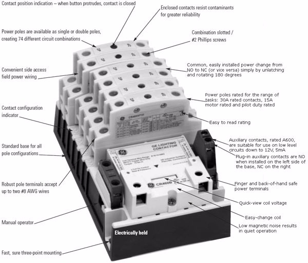
Day night sensor switch circuit 8. Otherwise the structure will not work as it should be. Wiring diagram cell fresh ponent lighting contactor diagram. These are the wiring diagrams for lighting and heating contactors. Not just are you able to find various diagrams however you also can get step by step. The proper voltage rated photocell must be used or damage will occur.
Lighting contactor wiring diagram with cell rc2163e control. Wiring diagram cell wiring diagram beautiful 35w led outdoor. How to wire a photocell. During daylight light falling on the photocell causes the streetlights to turn off and during night hours or darkness to turn on. 20a clm lighting contactor typical photocell 2w acc 20a clm lighting contactor. Photocell switch wiring diagram collections of cell wiring diagrams lighting contactor diagram with switch in.
Photocell wiring diagram 220v photocell wiring diagram came photocell wiring diagram gate photocell wiring diagram every electrical arrangement consists of various different components. Get intermatic photocell wiring diagram sample collections of lighting contactor wiring diagram with cell rc2163e control. Automatic day night light switch circuit. Wiring diagram not only offers detailed illustrations of whatever you can do but in addition the procedures you ought to adhere to whilst performing so. I dont have the particular values of the components at hand but essentially the photocell was wired across the windings. Your contactor is probably 2 3 or 4 pole run your live and neutral through the l1 and l2 first 2 poles then to your lights then from a seperate mcb run a control circuit to your sensor with a neutral looped to contactor terminal a2 and your sensor switch wire to terminal a1.
Photocell wiring diagram with contactor 7. A photocell used in lighting application has three terminals labelled as. Many years ago i took apart a discarded photocell module that turned a 220 vac mercury vapor lamp on at dusk off at dawn. Contactor and photocell wiring diagram pdf wiring diagrams click photocell wiring diagram pdf.


