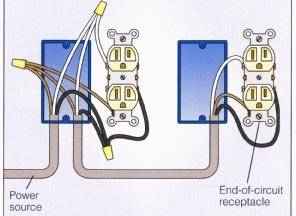
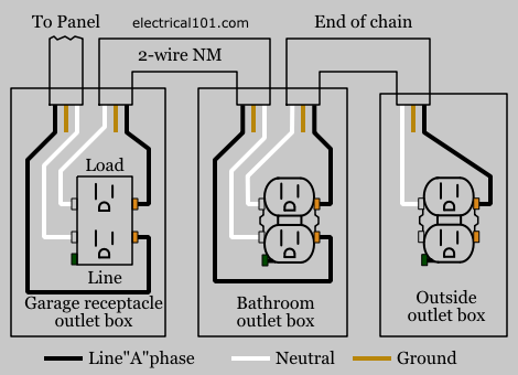
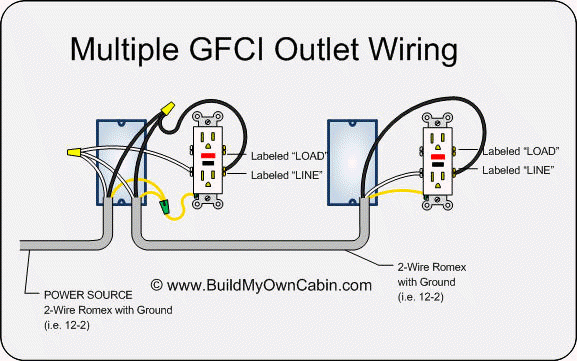
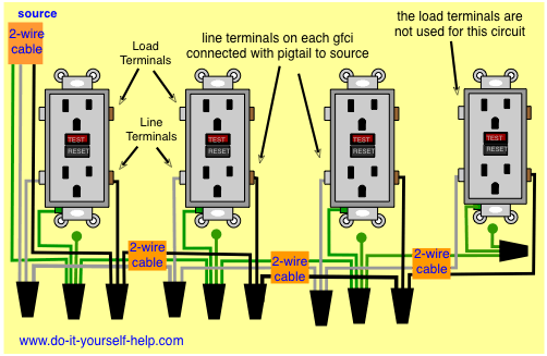
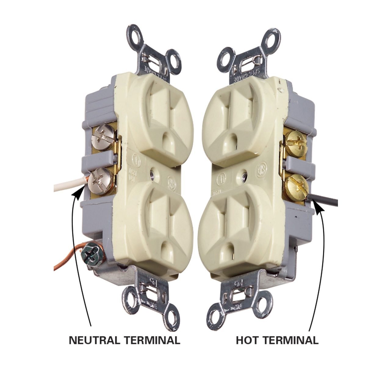
For wiring in series the terminal screws are the means for passing voltage from one receptacle to another. Another approach to outlet wiring is to create pigtails.
Wiring A Switch And Outlet The Safe And Easy Way Family
Multiple receptacle wiring diagram. Wiring a receptacle also referred to as an outlet is another of those fundamental wiring skills that every diyer should feel comfortable undertaking. To wire multiple outlets follow the circuit diagrams posted in this article. Multiple outlet in serie wiring diagram. Each outlet is independent of each others as they are wired to separate cables. Keep in mind that series connection of outlet is against the nec code also it doesnt make sense as if one of the outlet wires cuts or one faulty outlet will make the whole circuit. You create a pigtail by twisting together multiple wires of the same color its very important that theyre the same color and adding a short length of spare wire of that color.
Here 3 wire cable is run from a double pole circuit breaker providing an independent 120 volts to two sets of multiple outlets. This wiring is commonly used in a 20 amp kitchen circuit where two appliance feeds are needed such as for a refrigerator and a microwave in the same location. The 15a 125v receptacle is the most widely used device in your home. Twist clockwise using pliers then screw a wire cap onto the connection. Wiring diagram for dual outlets. In this simple wiring diagram multiple outlets have been connected in parallel.
Any break or malfunction in one outlet will cause all the other outlets to fail. In this diagram a 2 wire nm cable supplies line from the electrical panel to the switch outlet boxthe black wire line connects to a switch terminal and the black wire of a 3 wire nm cable that travels to the split receptacle boxthe white wire neutral connects to the white wire of the 3 wire nma 3 wire nm cable connects from the switch box to. This article and detailed wiring diagram explains the steps to wiring the common household receptacleoutlet. Alternate split receptacle wiring diagram. The neutral wire from the circuit is shared by both sets.
