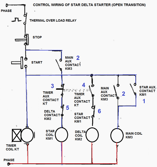
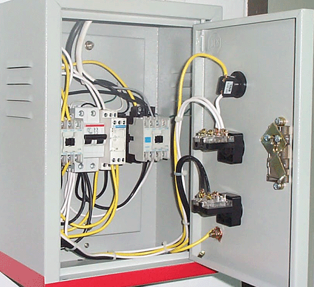
Timimng diagram of timer. Electrical earthing methods and types of earthing grounding.

Single Timer Wiring Diagram H1 Wiring Diagram
Magnetic contactor diagram with timer. Iec contactor specifications bulletin numbers 100104 k 100104 c 100104s c 100104 e 100s e 100104 d 100s d 100 g 100q c topic page. Magnetic contactor wiring diagram data wiring diagram schematic contactor wiring diagram. When we give supply to timer timer run and after completing set time t timers relay on. Each component should be placed and linked to other parts in particular manner. A simple circuit diagram either of the two start buttons will close the contactor either of the stop buttons will open the contactor. Timer has two element timer and relay.
On delay timer circuit diagram wiring diagram contactor with push button circuit diagram of delay timer on off power off delay timer circuit diagram 2 way lighting circuit triggering transformer push button fan switch light activated switch circuit diagram wd081 text. Air conditioner contactor wiring diagram air conditioner magnetic contactor full wiring contactor diagram diagram 4 way valve diagrams electric wiring free download diaphragm vacuum pu f4w fully4world magnetic contactor magnetic contactor wiring magnetic contactor wiring diagram outdoor unit wiring outdoor wiring with. Clap switch circuit using ic 555 timer without timer. Many large pieces of equipment are powered directly from high voltage lines. With help of following timing diagram we can easily understand working of timer. This book even contains recommendations for extra supplies that you may require in order to complete your projects.
Wiring diagram also gives beneficial recommendations for projects that might demand some extra equipment. Contactor wiring diagram with timer datasheet. Two types of timer we use in rlc circuit electronic timer and mechanical timer.


