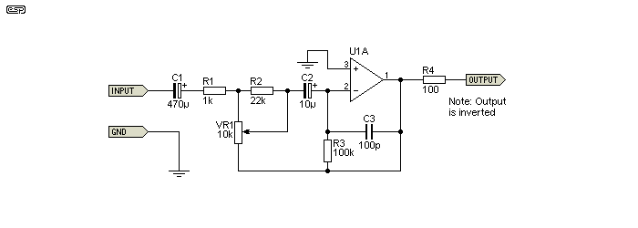
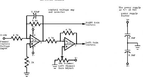
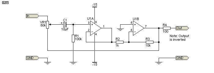
V oltage controlled volume circuit. 22 out of 100 based on 297 user ratings the simple automatic loudness control circuit diagram can be download for free.

Diagram Circuit Automatic Loudness Control Circuit
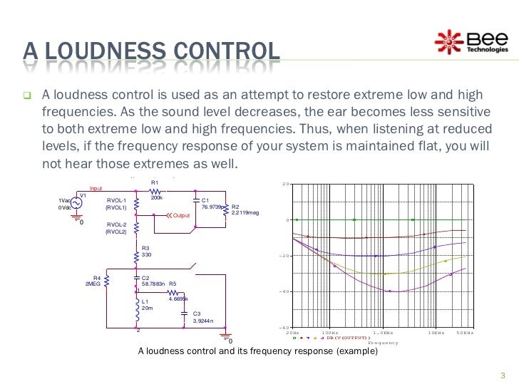
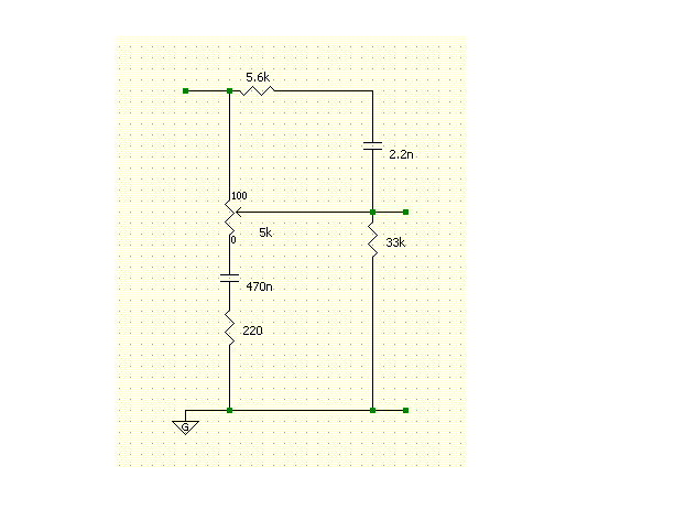
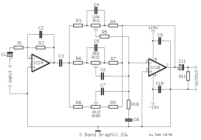
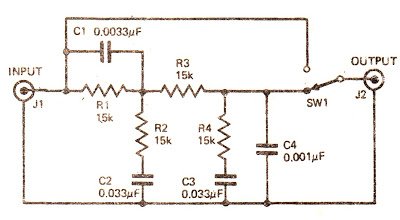
Loudness control circuit diagram. Simple automatic loudness control circuit diagram has been viewed 1290 times which last viewed at 2020 07 13 143427 and has been downloaded 1 times which last downloaded at 2014 07 07 112217 published by charlotte on 07 jul 2014. Stereo tone control circuit is used to adjust the tones before entering the audio power amplifier. Also it uses an integrated circuit op amp that is low many noises or low noise. Off off to use a bypass. 3 circuit diagram of the loudness control used by author. Now you can control the bass treble and volume by rotating three potentiometer on the circuit.
4 measured frequency response of the fig. Stereo tone control over equipped with a loudness and filter directly without using the switch to disconnected or connected. The circuit shown is for a single channel so for a stereo system two such units should be built. The basic approach with the circuit in figure 5 is. My friends want a tone control stereo circuit. This will serve as a low pass filter circuitvr1 is adjusted by the strength of the signal to the outputvr1 100k linear potentiometer which uses the.
His volume control circuit offers an unusual approach to the well known problem of distortion in active device attenuators. Stereo tone control with loudness and filter circuit diagram. It can control the sound bass treble volume well. The total resistance is 15kω. When the switch s1 to the on position the signal will flow through c10001uf c2001uf and r12k. 2 select the value of c2 so its reactance is lower at high and mid frequencies and.
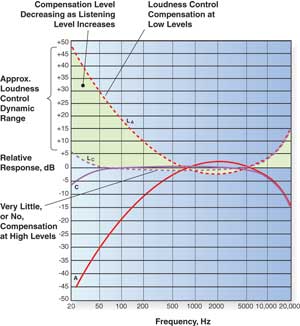
The heart of this digital volume controller dvc circuit is ic2 4067 16 channel analog multiplexer. This circuit has a boost of 13db at 20hz and approximately 9db at 20khz. R1 100k r2 50k trim r3 22k r4 15k r5. This circuit and wiring diagram. What we have really done is taken sound pressures along the 80 db loudness contour and moved them down to the 40 db level. And it is a high gain more than two circuits above.
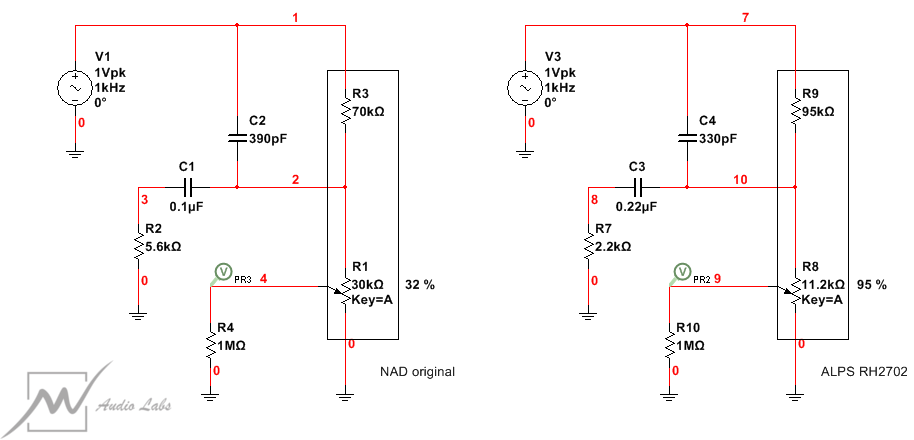
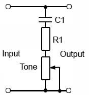
The zero output in this case is obtained by allowing equal signals of opposite phase to cancel each other. To operate the circuit connect the components as per the circuit diagram give 15v and 15v supply to tl072 opamp and give audio input from mobile by connecting 35 mm audio jack to the circuit. Because the 1kω has been connected between every input and output the multiplexer can act like a potentiometer. 1 use c1 to boost high frequencies where it is connected across the top half of the volume control when the loudness switch is on. Switch s1 is an option to use open on using loudness control. This loudness control alters the frequency response curve to correspond roughly with the equal loudness characteristic of the ear.
3 select r so that high and mid frequencies are attenuated. Then i found this circuit tone control stereo bass treble using two ne5532.

