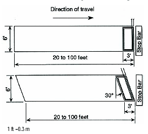
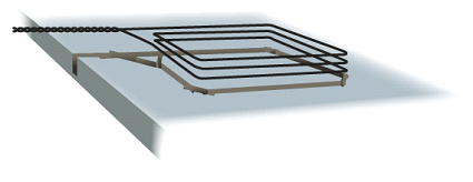
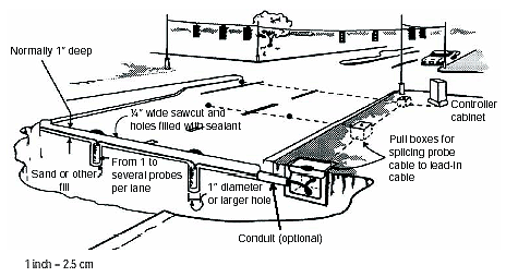
Loop installation tools supplies. Saw cut cut in loops.
Double Long Vehicle Magnetic Loop Detector Adjustable Sensitivity
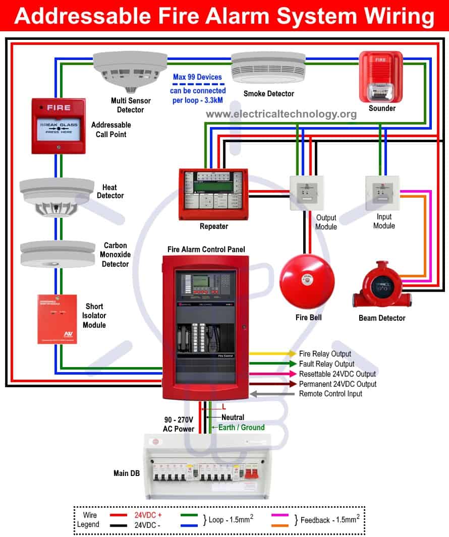
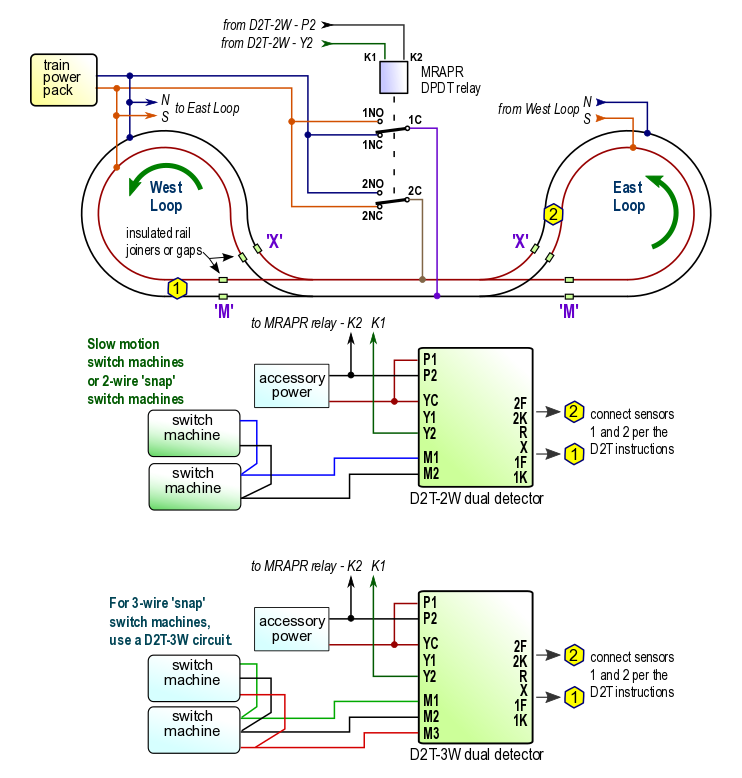
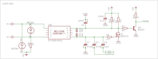
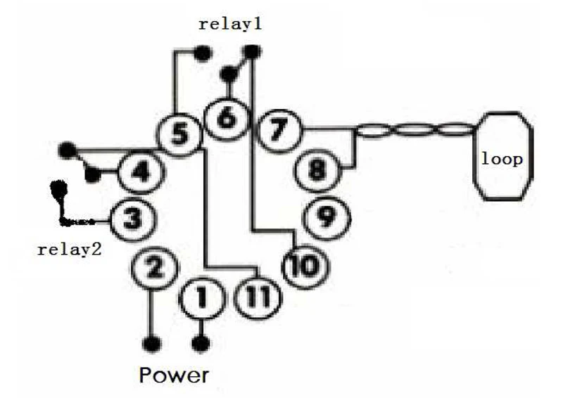
Loop detector wiring diagram. Sensor probes wands. A wiring diagram is a streamlined conventional pictorial representation of an electrical circuit. It shows the components of the circuit as streamlined forms and the power as well as signal links between the gadgets. This multi voltage vehicle detector solves the problem of not knowing which voltage to take for service a call or installation. A wiring diagram is a streamlined traditional photographic representation of an electric circuit. Collection of loop detector wiring diagram.
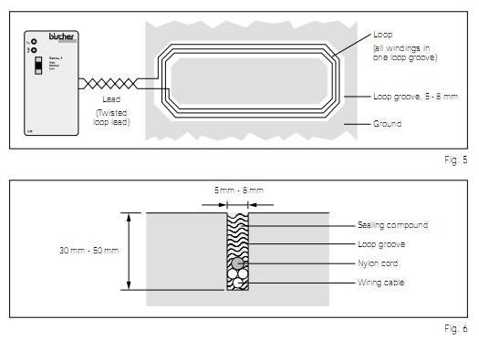
The feeder should be of the same material but twisted a minimum of 20 twists per meter. Reduce the cost of inventory by stocking only one loop detector with the universal voltage of our mvp d tek. Loop detector wiring diagram 38 loop detector operating instructions 38 1 38 6 remote control station pedestal 39 notes 40 operator field installation for assembled gate 41 42 operator field installation for unassembled gate 41 42 balance system adjustment and safety warnings 43 44. All you need is one detector in your stock room and on your truck. It reveals the parts of the circuit as simplified forms as well as the power and signal connections in between the devices. Direct burial pave over loops.
Assortment of loop detector wiring diagram. Pd132 loop detector specificationver100 6 installation information 61 loop and feeder specification the loop must consist of insulated wire with a minimum copper cross sectional area equivalent to 15 square millimeters. Torxun 20500048 4 x 8 preformed high temperature loop with 50 lead. Visit our loop detector loop diy center for detailed instructions and diagrams.
