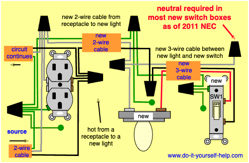
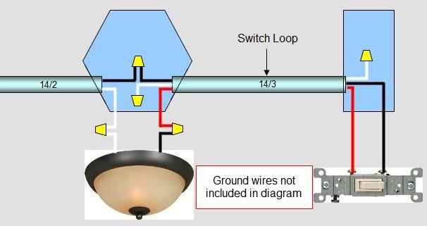
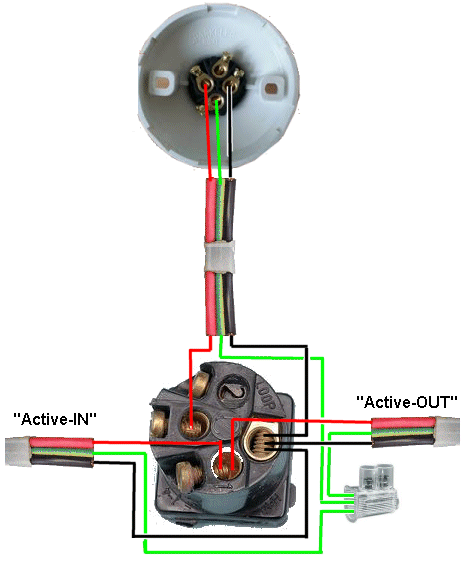
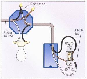
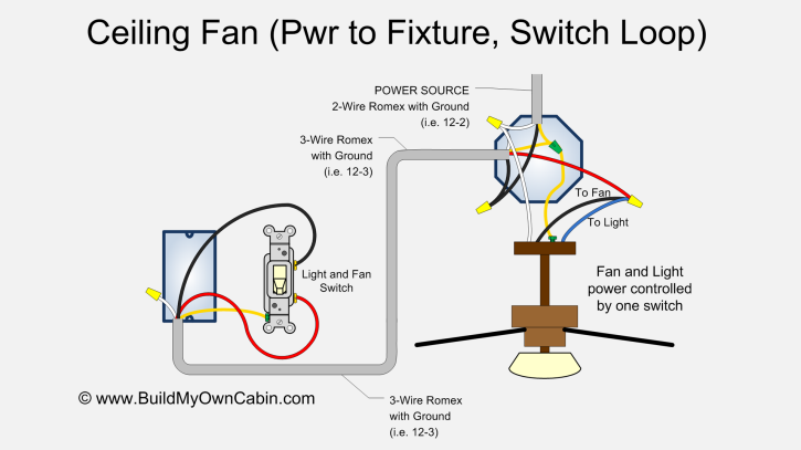
In a switch loop the hot and neutral wires arrive at the light fixture before reaching the switch. Instead we use a switch loop wiring pattern to control when you want the light on and off.

Wiring A Light Fixture Diagram H1 Wiring Diagram
Loop at the light wiring diagram. Multiple light wiring diagram. Student training aid for the connections required to wire a lighting circuit using the 3 plate loop in method. Landscape lighting wiring kit httpsgooglxk9hdr easy tree mount stakes down lighting httpsgoogldncm4u access all our online resources by following us on social media. Multi point loop in radial lighting circuit. Wiring diagram for loop in lighting new basic wiring diagram light electrical wiring and charging system help building circuitry layouts show the approximate places and also affiliations of receptacles lights and also irreversible electric services in a structure. Modern ceiling roses are designed to facilitate this method of wiring.
One way lighting circuit using loop in ceiling roses. The light wiring diagram shows how the live feed from the consumer unit fuse board shown in blue in fig 1 feeds into the first ceiling rose ceiling rose a fig 1. The hot and neutral terminals on each fixture are spliced with a pigtail to the circuit wires which then continue on to the next light. Without a switch wiring diagram it can be very easy to make a serious mistake that will cause the circuit to malfunction and possibly become a hazard. If you simply connected the wires from the light to the switch the light would always be on. Video explains the connection required within the ceiling rose one way switch and.
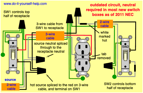
Wiring diagrams for switches wiring a light switch single switch wiring diagram 1 single. The source is at sw1 and 2 wire cable runs from there to the fixtures. 2 wiring for end of loop 2a this wiring arrangement would indicate that this is an end of the loop light fitting. The advantages of the loop in method is all the connections are accessible and can easily be inspected and maintained as per the current electrical regulations. This diagram illustrates wiring for one switch to control 2 or more lights. Line diagram of a one way lighting circuit using loop in.
It has one less live one less neutral and one less earth core because the loop in has reached the end and doesnt need to pass power on to another ceiling rose. Complete with a color coded trailer wiring diagram for each plug type this guide walks through various trailer wiring installation solution including custom wiring splice in wiring and replacement wiring. Understand that switching is just a loop of the hot wire regardless of the colors of the wires. Interconnecting cable paths may be revealed roughly where specific receptacles. This would be cable a in the diagram below fig 2 which shows how the ceiling rose is terminated. If your vehicle is not equipped with a working trailer wiring harness there are a number of different solutions to provide the perfect fit for your specific vehicle.

