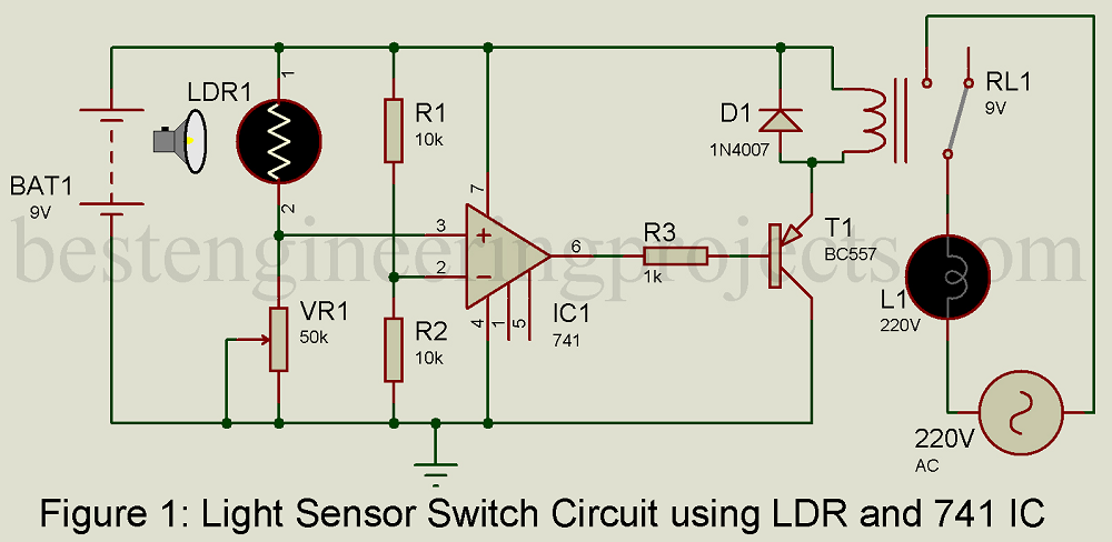
It has two internally frequency compensated operational amplifiers. A 230v ac supply is provided to the load in this case the load is represented with a lamp.

Motion Sensor Light Switch Envirementalb Com
Light sensitive switch circuit diagram. High resistancevr1 more darkness to switch off the led. The comparator ic lm358 and the ldr. We can adjust the sensitivity using the preset vr1 10k. As the light level increases and ldr meets the lowest threshold resistance the circuit automatically turns on the led d1. Light switch circuit diagram. If desired operation reverse position in the scheme of the.
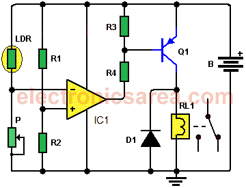
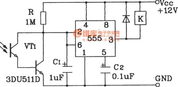
Switching point of the light sensitive switch may be adjusted from p1. The task of installing additional wiring for a light switch and new light fixture will depend on available access to the proposed location. It contains a 10k va. The lm358 ic has 8 pins and can have supply voltages ranging from 3 32 volts. The light sensor circuit is an electronic circuit designed using light sensor ldr darlington pair relay diode and resistors which are connected as shown in the light sensor circuit diagram. This is dark sensitive and light activated switch circuit in this circuit ldr light dependent resistor is used to sensing the light and darkness.
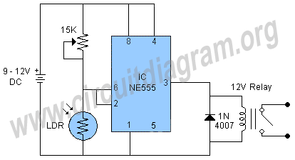
This circuit is simple compared to other light sensitive switching circuits it switches a relay so that you can switch electrical appliances also with it you can use the circuit for garden lamps or outdoor or indoor lighting. Less resistancevr1 less darkness to switch off the led. If you want more flexibility replace p1 with one that has a value of 1 mω. The light activated switch circuit mainly consists of two components. This basic light sensor circuit is of a relay output light activated switch. The figure 4 circuit is very sensitive and can detect light level changes too small to be seen by the human eye.
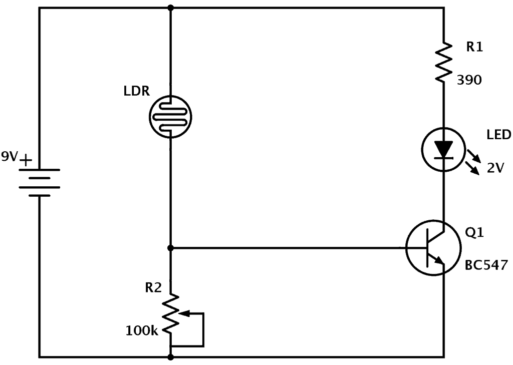
At night time all leds glow and in daytime when light falls on ldr all leds switch off automaticallyproject of light activated switch circuit diagram using transistor. Hiring a qualified electrician will ensure that the installation is performed correctly where the existing circuit wires will be identified and new circuit wiring will be extended to the new light switch. With the potentiometer set the minimum minimal resistance lamp will light a crepuscular light. A potential divider circuit is formed between the photoresistor ldr and the resistor r1when no light is present ie in darkness the resistance of the ldr is very high in the megaohms mω range so zero base bias is applied to the transistor tr1 and the relay is de energised or off. Light sensor circuit working operation. A light detector senses light.
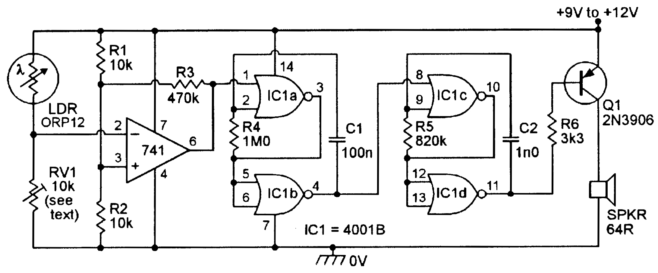
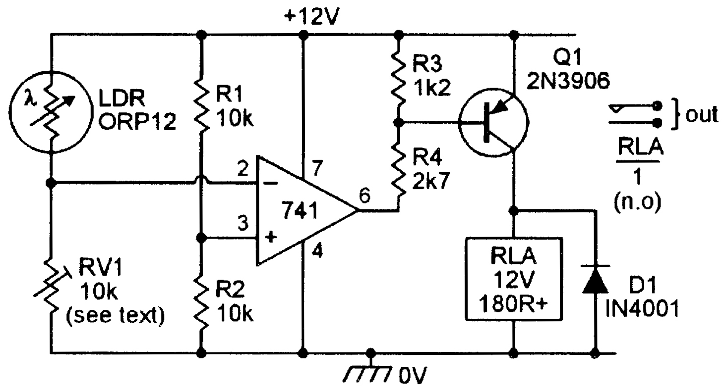
The circuit can be modified to act as a precision dark activated switch by either transposing the inverting and non inverting input terminals of the op amp or by transposing rv1 and the ldr. Light activated switch circuit design.


