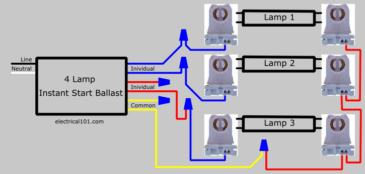
Changing the wiring on a fluorescent light fixture from series to parallel involves changing the ballast from a series to a compatible parallel ballast. Depending on the light fixture and how it is mounted it may be easier and about the same price to replace the fixture instead of the ballast.
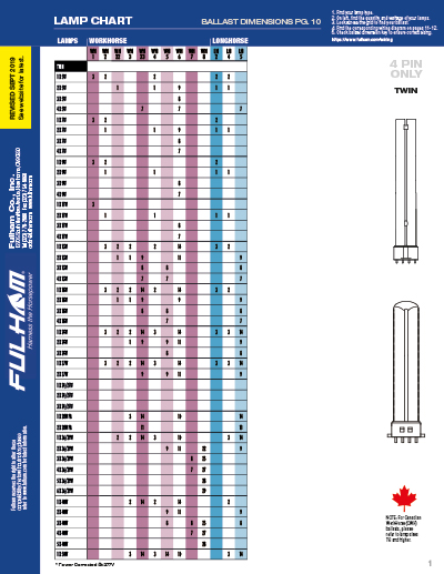
Fulham Wiring Diagrams
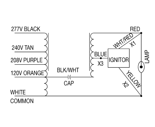
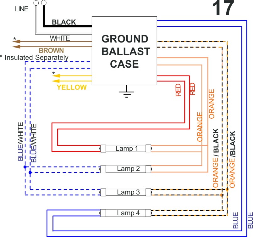
Light ballast wiring diagram. So how to wire the new ballast to my fixture so it works. Pulse start ballast troubleshooting. Match replacement ballast wiring to original ballast wiring. As an example a switch will be a break in the line with a line at an angle to the cable a lot like a light switch you could flip on as well as off. Remove the ballast from the. A wiring diagram is a simplified standard photographic depiction of an electrical circuit.
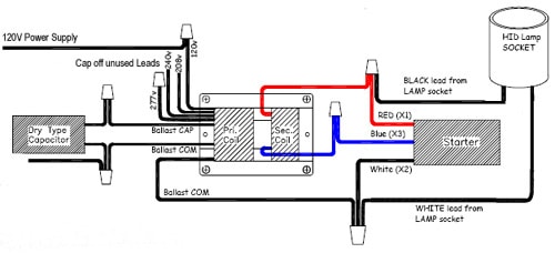
Variety of 2 lamp t12 ballast wiring diagram. Metal halide ballast wiring diagram gallery. Remove the fluorescent ballast compartment cover to expose the internal wiring and ballast. Its purpose is to show you step by step how to convert your current 4 foot t8 or t12 fluorescent tube light fixture to use the starled ballast. Replace the ballast when your fluorescent light flickers or makes an annoying hum. It reveals the components of the circuit as streamlined forms and the power and also signal links in between the gadgets.
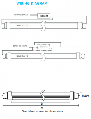
Wiring diagram how to bypass ballast for led tube. Assortment of fluorescent ballast wiring diagram. Cut back additional wiring on opposite side of ballast as the led tube lamp only requires power at one end. Series ballasts can only be wired in series according to the diagram on the ballast. In many t8 fixtures the ballast is covered by a casing and the t8 tubes are on top of it meaning you need to take out the tubes and unscrew the casing to get to the ballast. Unplug the fixture or turn off the power at the main panel.
Look at the number of wires and to what they are connected in the current light fixture. 1000 watt ballast wiring diagram elegant hid ballast wiring diagrams. The repair will only take about 10 minutes. A wiring diagram printed right on the ballast surface. Follow the colore coded wiring diagram was the recommendation yet after connecting all like colors on the new ballast to the fixture all i got was a delayed dim light at the base of each fluorescent bulb. Ballast wiring diagram shows how the ballast is wired to the lamps ballast wiring diagram.
A new garage fluorescent light fixture could cost less than a replacement ballast. A wiring diagram is a streamlined standard pictorial representation of an electric circuit. Remove any covers case lenses or lamps that block your access to the ballast and set them aside. Parallel ballasts can only be wired in parallel according to the diagram on the ballast. It reveals the components of the circuit as streamlined shapes and also the power and also signal connections between the devices. The attachment method.
A resistor will certainly be. I suspect the wiring is not as simple as described. Take photos make a drawing do not fail to record this information as it makes wiring a new ballast far easier.
