The brightness of an led is directly dependent on how much current it draws. Try flipping it around.

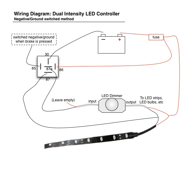
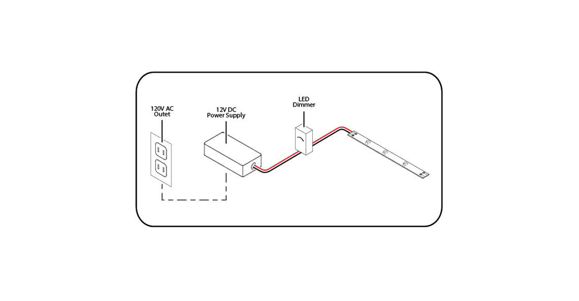
Bluewaterled Dimmer On Off Control
Led wiring circuit. I figured that would allow me to mix and match and make enough different voltage. So dont freak out if adding an led breaks your circuit. 230v led driver circuit principle. Circuit 3 of simple led circuits leds in parallel the final circuit in the simple led circuits tutorial is leds in parallel. Led current in amps 125 r3 so for a current of 550ma set r3 to 22 ohms youll need a power resistor usually r3 power in watts 156 r3 this circuit also has the drawback that the only way to use it with a micro controller or pwm is to turn the entire thing on and off with a power fet. The basic principle behind the 230v led driver circuit is transformer less power supply.
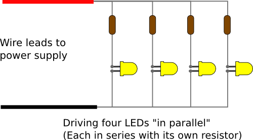
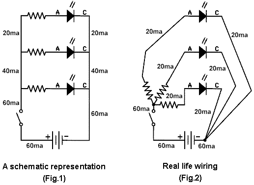
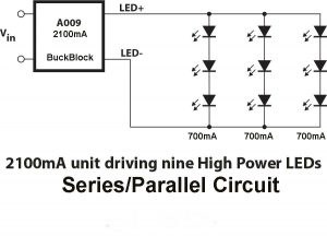
The circuit diagram for leds in parallel connection is shown in the following image. In this circuit we will try to connect three 5mm white leds in parallel and light them up using a 12v supply. This led calculator will help you design your led array and choose the best current limiting resistors values. The led symbol is the standard symbol for a diode with the addition of two small arrows denoting emission of light. 2 moar current equals moar light. Assortment of t8 led tube light wiring diagram.
To get started input the required fields below and hit the design circuit. Hence the name light emitting diode led. A reversed led can keep an entire circuit from operating properly by blocking current flow. Here is a list of those parts. Power supply voltage v. You need several parts in order to build a basic led circuit.
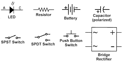
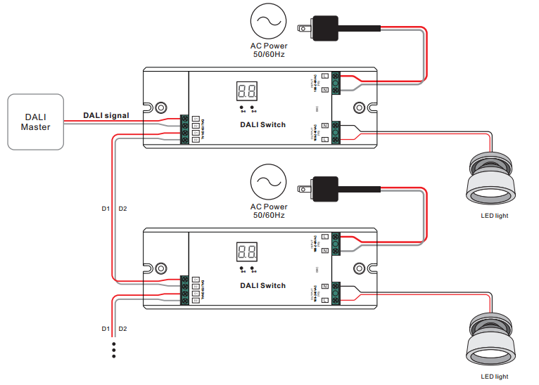
It shows the parts of the circuit as streamlined forms and also the power and signal connections between the gadgets. Hopefully those looking for practical information on electrical circuits and wiring led components found this guide first. Four 15 volt aa batteries make sure theyre fresh one four battery holder for aa batteries one battery clip one 22 identified by a red red red stripe pattern and then a. The circuit diagrams or schematics that follow are drawn using industry standard electronic symbols for each component. And the only way to change the. Symbol definitions are as follows.
That means two things. Circuits are the building blocks of electronics projects. 2760307 5mm red led 17 v 2760351 5mm yellow led 21 v 2760036 flasher red led 5 v 2760041 2 pack red led 26 v 2760086 jumbo red led 24v power supply i really didnt know what i would need to power them so i bought some 9v batteries and some 15v aas. The main component is the x rated ac capacitor which can reduce the supply current to a suitable amount. Its likely though youve already read the wikipedia page about series and parallel circuits here maybe a few other google search results on the subject and are still unclear or wanting more specific information as it pertains to leds. A wiring diagram is a simplified standard pictorial representation of an electrical circuit.
