The easiest and quickest way to supply the extractor would be from the cooker switch into a fcu with 3amp fuse is this acceptable. It can also be adapted for separate switching if required.
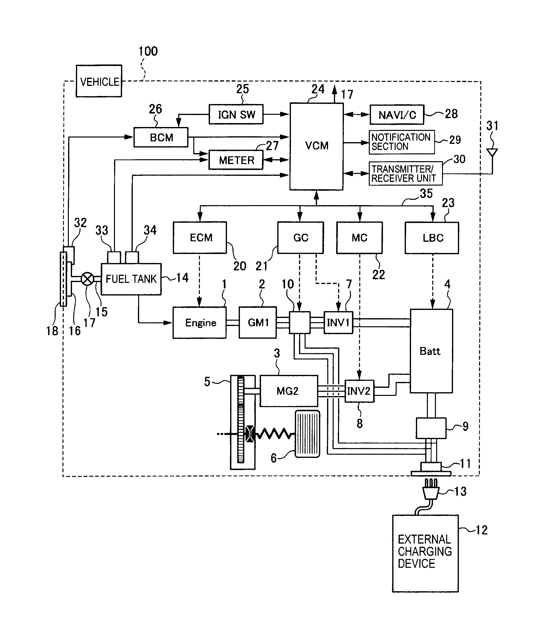
Broan Bathroom Fans Wiring Diagram H1 Wiring Diagram
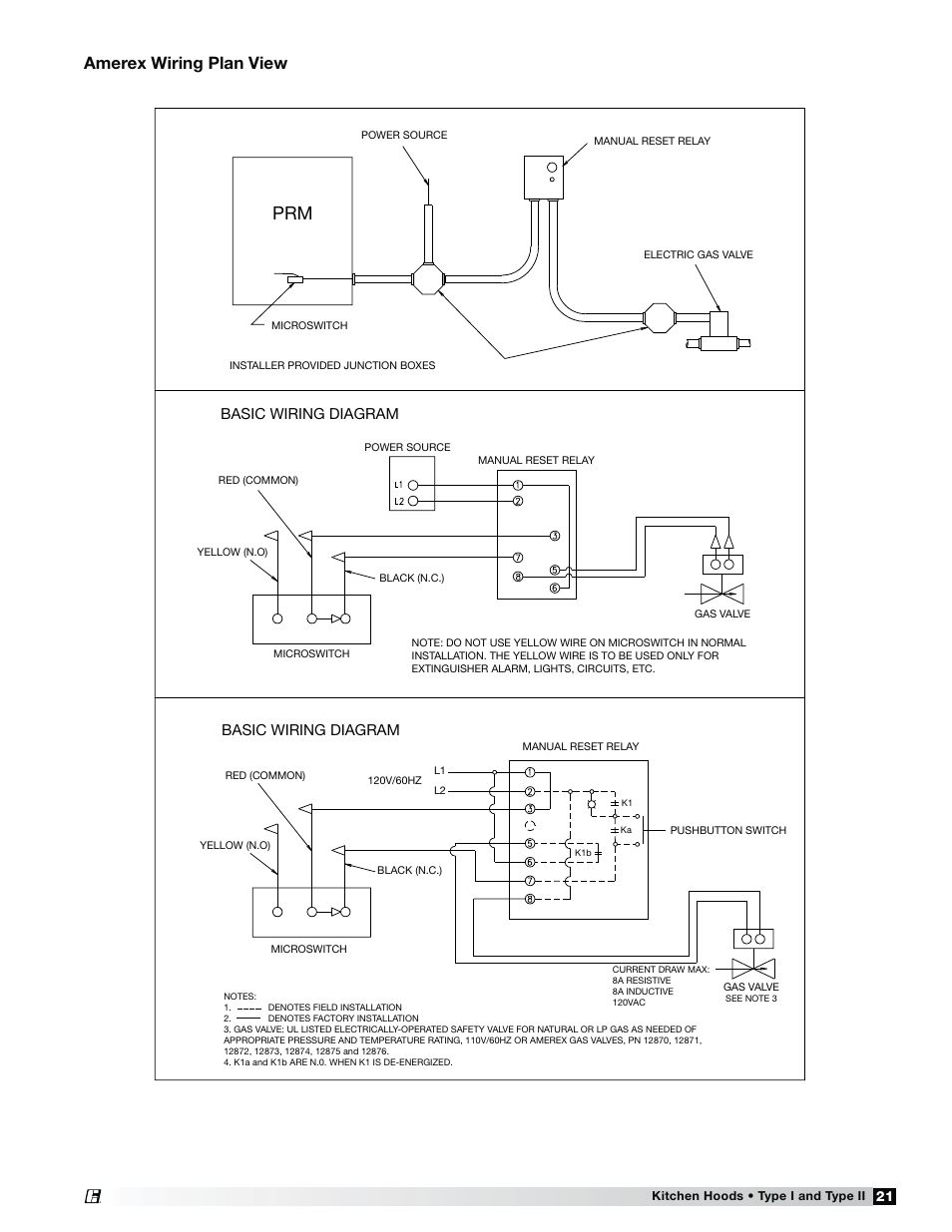
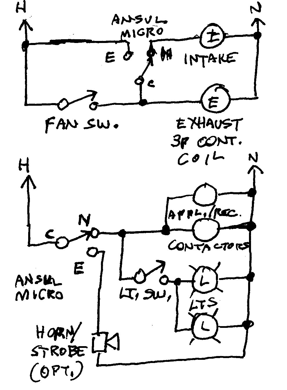
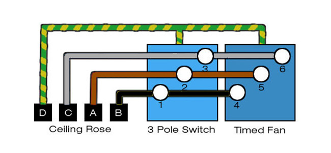
Kitchen extractor fan wiring diagram. Above the cooker roughly in the middle of the wall is a large metal cover plate quite old after removing the cover plate found a terminal block connecting the 6mm supply cable from the cu to 6mm cable going to. Er 1 2 4 5 diagram er4 diagram er7 diagram er6 diagram er5 3ø wiring diagrams 1ø wiring diagrams w2 orange brown blue black red grey w2 u2 u2 v2 v2 u1 u1 v1 v1 w1 w1 l1 l1 l2 l2 l3 l3 e e two speed motors high speed low speed orange brown blue black red grey m 1 m 1 l l n n e e 3 active wires plus. Uk wiring only may not be the same in your country so you must check with your local building regulations. This wiring plan will simply run the fan when the room light is on. Exhaust fan switch wiring diagram wiring diagram. How to wire a 3 pole fan isolator switch.
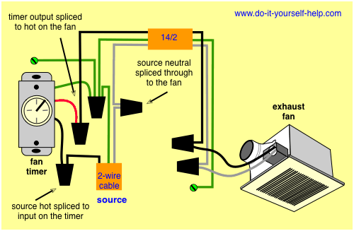
Options include a manual pull switch and a vacuum time lag switch. Known as afci arc fault circuit interrupters these devices are designed to sense sparking arcing that occurs when electricity jumps between faulty wire connections. There are several different types of extractor fans available kitchen extractor fans normally incorporate a cooker hood and are used to expel cooking smells and steam outside. Beginning with the 2014 national electrical code revision and extended in the 2017 revision a special type of circuit protection became required for many circuits in the home including the kitchen. However it is something that most people are capable of doing. Cook top and light fan wiring diagram 14 14 petraoberheit de.
Wiring a kitchen extractor fan. I explain the wiring using basic wiring. In this video i show how to wire a 3 pole fan isolator switch for a timer fan using 3 core earth cable and for a non timer fan using twin earth cable. Running along the floor out of sight underneath the fan area is a kitchen ring that comes directly out of the fuse box and terminates at one double socket at the other end of the kitchen. The time lag switch will allow the fan to be manually started but then run for a pre set time. Inline fan diagram idq elliesworld uk.
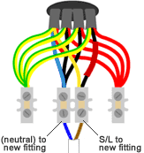
A normal cooker hood would be wired up like the diagram here there will be a switched fused connection unit leading to either a. The fuse box is marked kitchen ring even though only one socket is used on it. Wiring an extractor fan is not a task that most people will feel comfortable doing themselves. With just a basic understanding of electrics and a good sense of safety you really shouldnt have a problem wiring up these extractor fans. Wiring diagram for kitchen extractor fan wiring diagram. Extractor fan switch install wiring explained.
Wiring diagram for bathroom fan wiring diagram. Delta series twin fan a 2223 diags.

