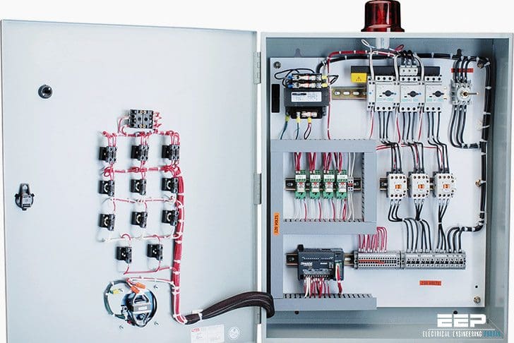
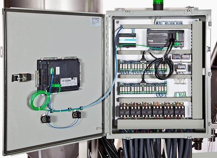
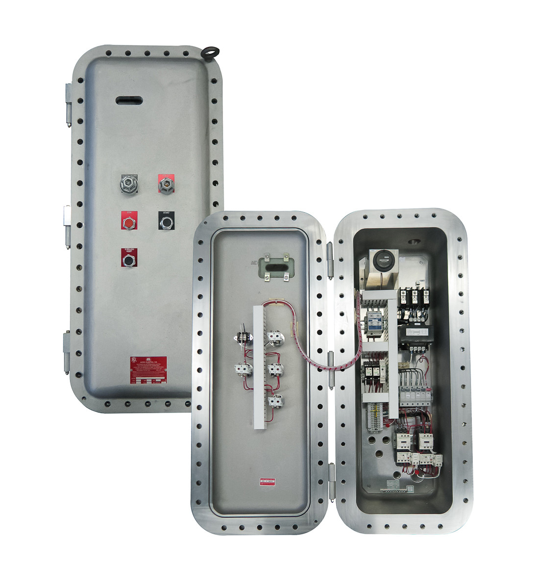
Control panel build series part 17. Control panel design for industrial equipment and machinery is an important undertaking resulting in an interface designed to control a machine or process.

How To Follow An Electrical Panel Wiring Diagram Realpars
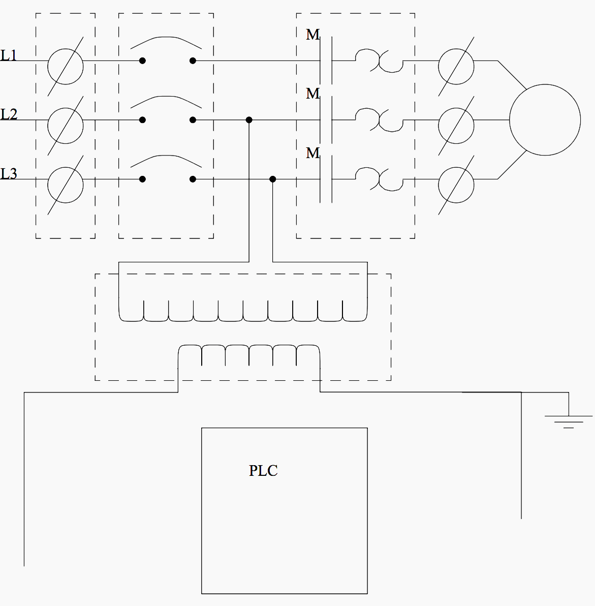
Industrial control panel wiring diagram. This type of diagram is like taking a photograph of the parts and wires all connected up. Lets go back and have a look at the control panel and try and figure out some of the connections by following a wiring diagram. It goes exactly the same for the other switches that we have here as well. Wiring power distribution rsp supply. These numbering schemes are often particular to each facility but there are tools to help make wire labels that will appear in the final controls cabinet. Many people can read and understand schematics known as label or line diagrams.
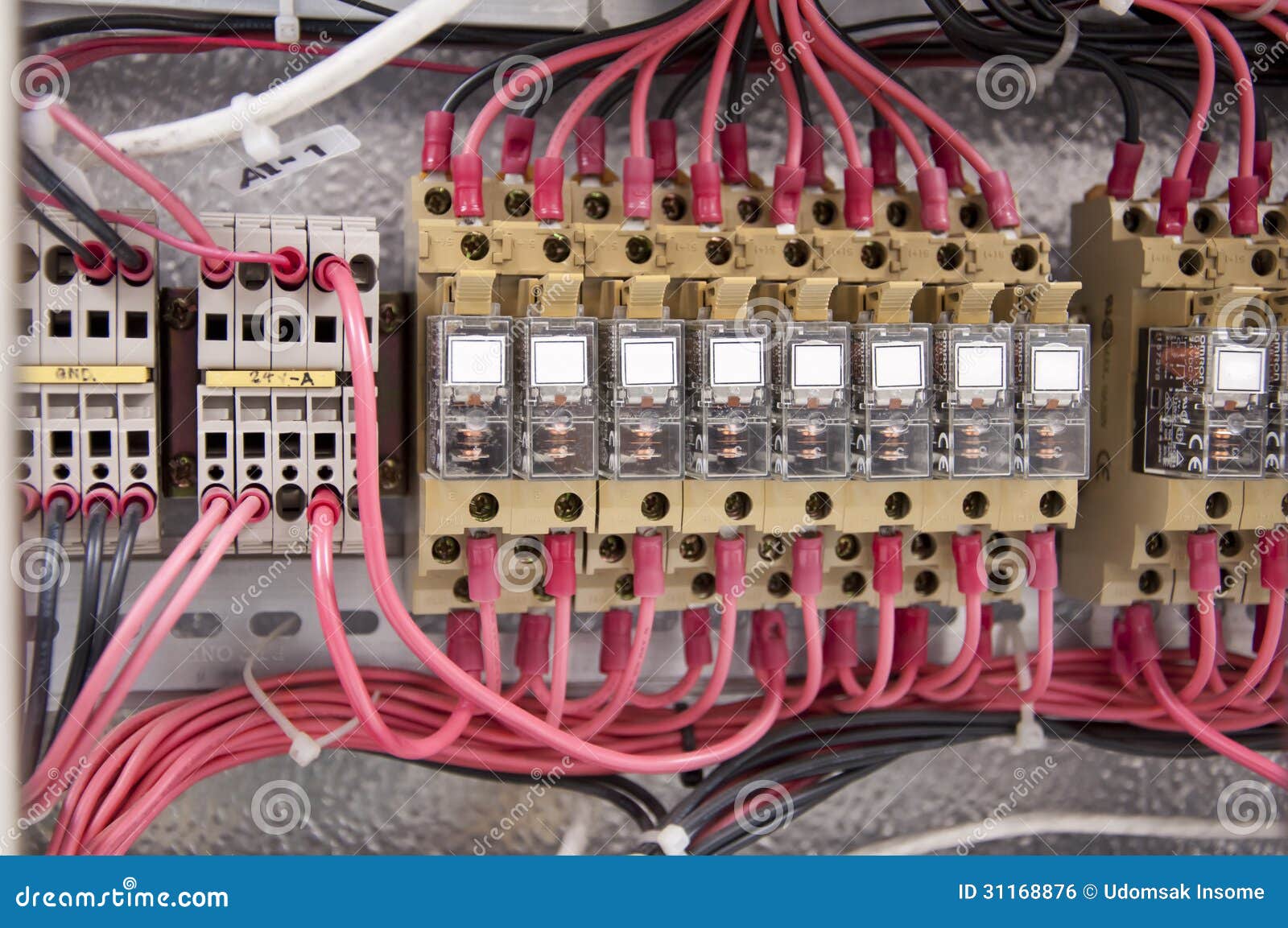
So this is how easy it is to read the wiring diagram for a control panel. Industrial control panels in depth. Three phase dol starter control overload indicator power wiring diagram. These diagrams show the actual location of parts color of wires and how they are connected. Wiring diagrams help technicians to see how the controls are wired to the system. Industrial control panel design schematics.
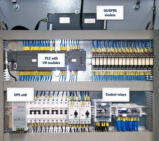
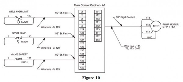
Its not a simple matter of selecting an appropriate enclosure and a back panel that houses the electrical hardware. So to sum it all up here is what you are going. As ive mentioned in the previous articles this is a control panel that is used for a system that turns wastewater into clean water. This is essential for industrial control systems that may contain hundreds or thousands of wires. It is a 2 door control panel on the front of which we have some switches that are connected to the plc inputs and outputs. The diagram also shows numbering for the wires in the device.
