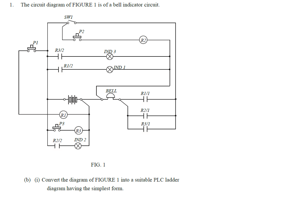
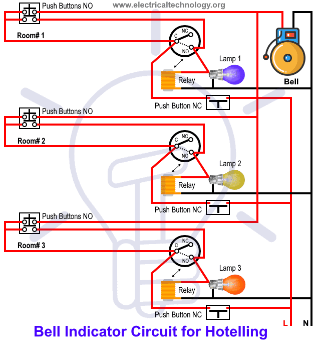
Overloadindicator and power wiring diagram. When a guest presses the push button the specified indicator with room number starts to glow with ringing bell at the hotel management and attendant panel.

Indicatorlights
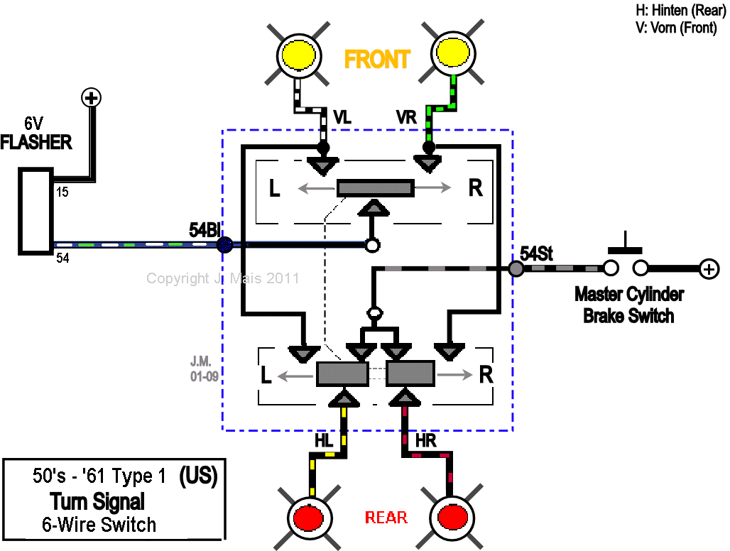
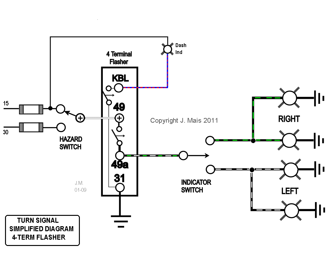
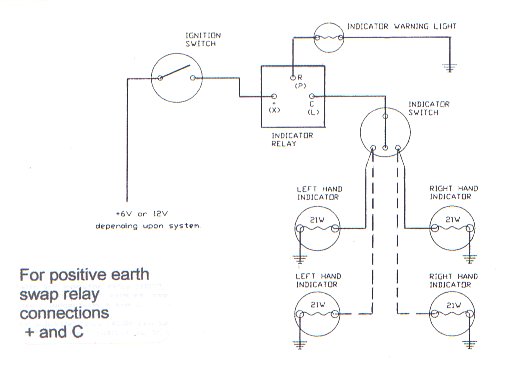
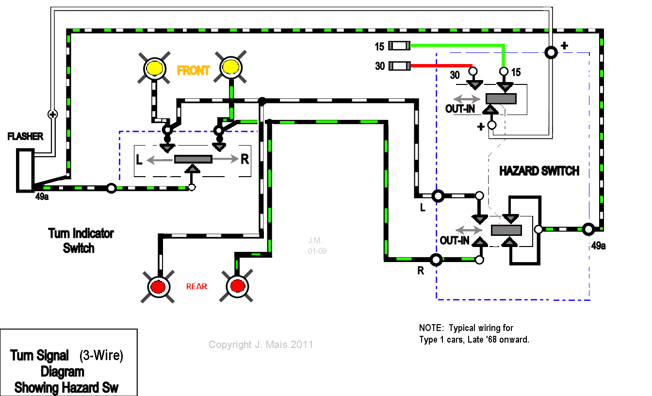
Indicator circuit wiring diagram. 120 and 240vac led voltage indicator circuit diagram circuit and wiring diagram download for automotive car motorcycle truck audio radio electronic devices home and house appliances published on 13 jul 2014. Externally the only difference is in the connection for the dash indicator. Hostel wiring circuit diagram and working it can be used to find the exact location and room where the guest needs attendant help. This diagram shows the turn signal flasher circuit in its simplest form. A bulb flasher circuit is a very common circuit which most of us would have come across in our day to day life. Yellow redwhite main feed.
We offer led indicator wiring diagram here due to the fact that it will be so very easy for you to access the web service. Dol starter connection dol starter control. Dol starter motor connection dol দখন কভব ডল কনকশন. Later the 4 terminal flasher relay was replaced with a somewhat simpler 3 terminal design. One very obvious example is the indicator lights on our automobilesas soon as the indicator is singled the bulb inside the indicator. This is the safer better way to wire leds in parallel with resistors and also ensures that you dont make the mistake that i did accidentally.
You can locate increasingly more experience and also knowledge exactly how the life is undergone. The led indicator wiring diagram content as well as motif of this circuitry layout really will touch your heart. 1 indicator wiring diagram. Grey black pilot. Resistor 330ω 4. Transistor bc547 4.
2 multipurpose light switch connections. Blown fuse indicator circuit diagram the emitter current of q2 is limited by q3 which turns when the current reaches about 10ma to shunt base current away from q2. Class project for today adapt the circuit above so it does the same job with only 1 flasher relay like most cars do hint hazard switches have more than two poles wiring diagram for hazards and indicators. Before we get into the 24v flasher relay circuit diagram and working of the circuit let us make a small practical observance. Here water level indicator alarm circuit designed by using few easily available components this tank water level alarm can be used in any type of house hold water tank and by proper implementation of this circuit we can avoid loss of overflow water. To simplify things cut off the plugssockets leaving the wires protruding from the plastic sheath.


