The type of control you perform every time you walk into a dark room. A wiring diagram is a streamlined standard photographic representation of an electrical circuit.

3 Wire Spdt Toggle Switch Wiring Diagram Free Download
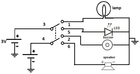
How to wire a dpdt toggle switch diagram. Below is an example of a circuit which utilizes a double pole double throw switch. An onoff switch can be implemented by simply sticking an spst switch in series with a power line. When the dpdt switch is switched one way flipped upward in the diagram the lamp and buzzer are both on while the led and speaker are off. Below is the schematic diagram of the wiring for connecting a dpdt toggle switch. This is how you wire a double pole double throw dpdt switch. 6 pin dpdt switch wiring diagram on off illuminated rocker switch wiring diagram to double pole throw rh natebird me carling dpdt rocker switch wiring diagram dpst switch wiring diagram.
It reveals the components of the circuit as simplified forms and also the power as well as signal links in between the devices. Variety of 6 pin dpdt switch wiring diagram. 2 methods are explained with associated wiring diagrams. At the end of the blue jumper attach another disconnect terminal. Remove all electrical power from the power source. The wiring diagram to the right will show how to wire and power this 12v 20amp on off on 3 way carling contura rocker switch.
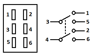
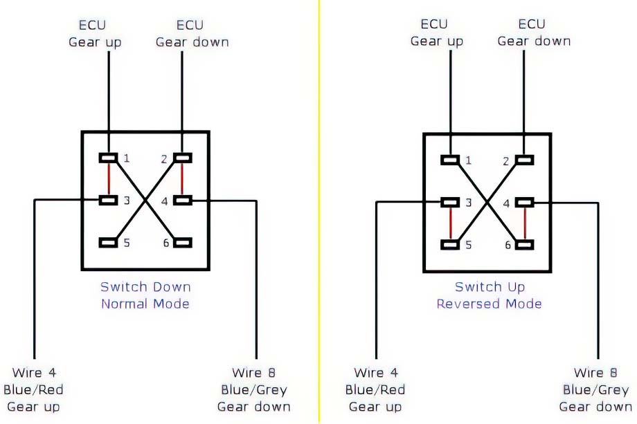
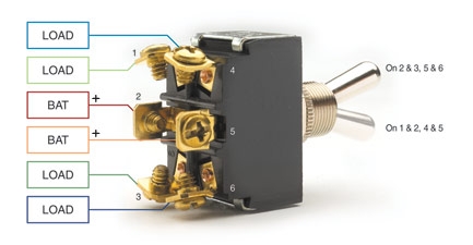
Use the wire strippers and remove ¾ of an inch of the wires insulation to reveal bare copper. Do the same for the brown wire. Dpdt toggle switch wiring. We will now go over the wiring diagram of a dpdt toggle switch. Then push this into the disconnect terminal and crimp with the wire tool. You can see above how a double pole double throw switch can allow a circuit to be in 1 of 2 modes.
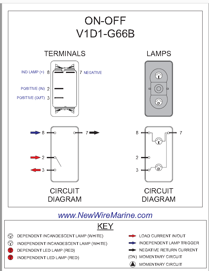
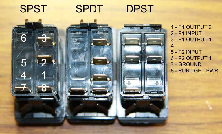
Assortment of on off on toggle switch wiring diagram. Do this on all wires that are being connected to the dpdt switch. This is a double pole double throw dpdt momentary illuminated momentary rocker switch it has one ind lamp at the top. Twist together one end of the blue jumper wire and the end of the main blue wire. Terminals 3 and 4 represent the toggle switch. In this video i give you the characteristics of a dpdt switch and how to wire.
These terminals receive the power necessary to drive the loads on. A dpdt toggle switch has 6 terminals. Connect the positive power wire from the power supply to one of the center screw terminals. Usually the onoff switch will be maintained like a toggle or slide switch but momentary onoff switches can have their purpose.
