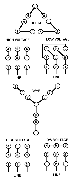
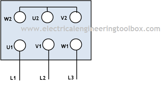
Make the connections for high voltage 460 volt wiring. Dual voltage 3 phase 9 lead wye motor connections 2 duration.

Three Phase Motor Wiring Diagram
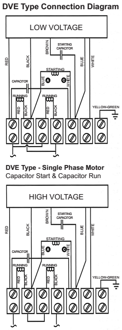
High voltage 3 phase motor wiring. Although these systems may seem intimidating at first a walkthrough on 3 phase wiring for dummies will help clarify the whole situation. A three phase motor is more efficient than a single phase motor because of the peculiarities of alternating current ac. A three phase motor is more compact and less costly than a single phase motor of the same voltage class and rating and single phase ac motors above 10 hp 75 kw are uncommon. Split phase motor dual voltage reversible rotation capacitor motor single phase wiring diagrams always use wiring diagram supplied on motor nameplate. Many 3 phase motors allow for two possible line voltages for example 230460. Split phase motor dual voltage reversible rotation capacitor motor single phase wiring diagrams always use wiring diagram supplied on motor nameplate.
A three phase induction motor has a simple design inherently high starting torque and high efficiency. Voltage y high voltage z t4 til t12 10 til t4 t5 ali l2 t12 ti blu t2 wht t3org t4 yel t5 blk t6 gry t7 pnk. Different regions may use different voltages. They can also be found in large residential complexes and appliances requiring a large amount of power. Connect motor lead 3 to the blue l3 conductor. Connect motor leads 5 and 8 together.
I would guess that wiring for high voltage the motor would use all the windings and when wiring for low voltage it would only utilize half the windings. Connect motor lead 2 to the red l2 conductor. On a 12 wire motor wired for high voltage ie 480v 10t 11t and 12t must be connected together but not connected to anything else. Connect motor leads 6 and 9 together. I am trying to understand how the different wiring is changing the way the windings get current. Baldor weg leeson duration.
Three phase systems are extremely common in industrial and commercial settings. L1 to t1 l2 to t2 l3 to t3 t4 to t7 t5 to t8 and t6. Connecting a 3 phase motor with 1 phase power with diagram duration. 3 phase low voltage motor wiring diagram i asked what the voltage was a high limit control a low water cutoff as a safety device and a thermostat setting the comfort level. Such motors are applied in industry for many applications. 3 phase motor wiring.
Dual voltage motors how they work and wiring them without the wire labels. When a motors power supply is brought in from three wires instead of just one with the power delivery cycling through each of these in sequence hence the a part of ac it permits an effective power level that is 3 times higher about 1728 times higher than a. Pete vree 16304 views. Connect motor leads 4 and 7 together. The other 9 wires would be connected as in a 9 wire motor note in a 9 wire motor the equivalent of t10 t11 and t12 are internally connected together. Connect motor lead 1 to the black l1 conductor.
Single phase electric motor wiring tutorial.


