Air compressor or float pump3ph starter1ph motor line voltage control magnetic starter controlled by a air compressor pressure switch nc. A wiring diagram gives the necessary information for actually wiring up a group of control devices or for physically tracing wires when trouble shooting is necessary.

Run Stop Relay Circuit
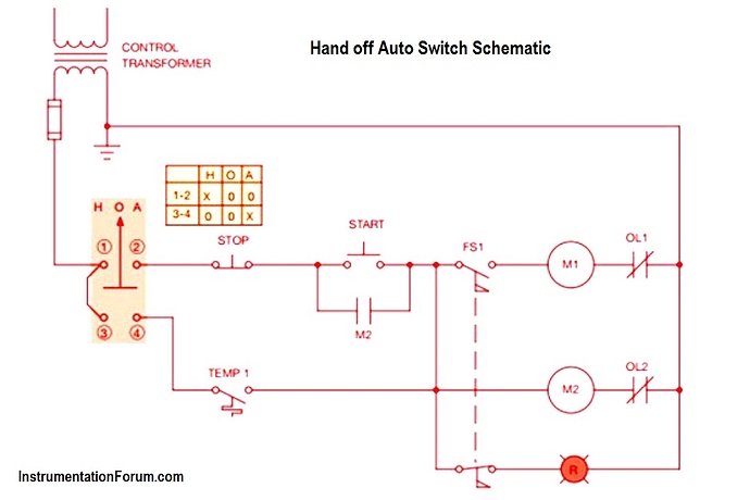
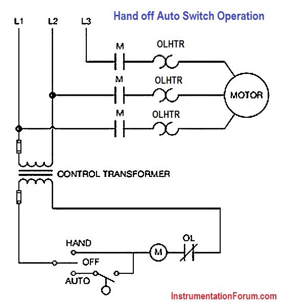
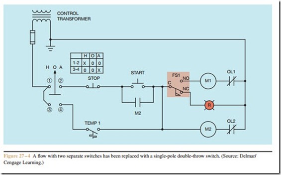
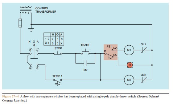
Hand off auto motor starter wiring diagram. If not the structure wont work as it ought to be. You can save this pic file to your individual laptop. Each part should be placed and linked to different parts in specific way. The switch is shown as a single pole. Hand off automatic controls are used to permit an operator to select between automatic or manual operation of a motor. In this guided application exercise well wire up and test the two wire magnetic motor starter hand off auto circuit we introduced in a previous lecture.
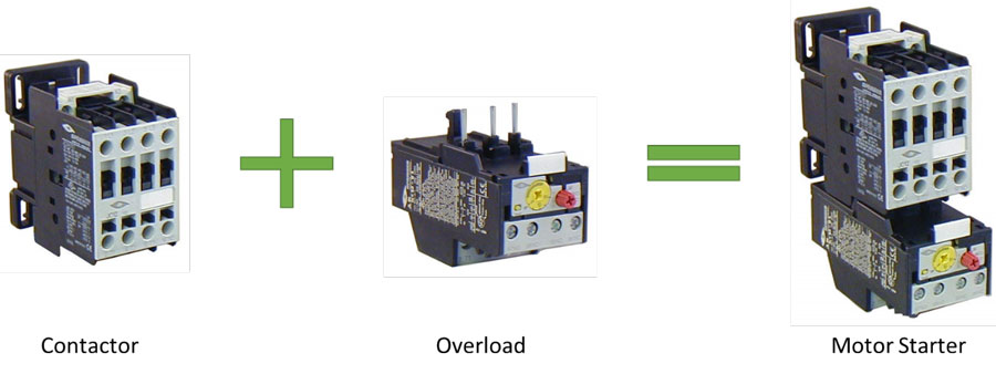
Square d motor starters wiring diagram sq d motor starter wiring diagram square d 3 phase motor starter wiring diagram square d 8536 motor starter wiring diagram every electric structure is composed of various distinct pieces. Hand off automatic controls recognize hand off automatic switches on a schematic diagram. A motor starter is a combination of devices used to start run and stop an ac induction motor based on commands from an operator or a controller. Our people also have some more graphics related to hand off auto switch wiring diagram please see the photo gallery below. Additionally well examine this circuits. Wiring diagram parts list design worksheet duration.
Wiring a two wire magnetic motor starter hand off auto circuit duration. A line diagram gives the necessary informa tion for easily following the operation of the various devices in the circuit. The electricity that passes through the contacts of the starter through the overload relay and out to the motor is called the power. There are two circuits to a starter the power circuit and the control circuit. In north america an induction motor will typically operate at 230v or 460v 3 phase 60 hz and has a control voltage of 115 vac or 24 vdc. Includes autohandoff control and low oil switch nc.
Please right click on the image and save the graphics. Basic wiring for motor contol circuitry of a starter the two circuits of a motor starter are the power and con trol circuits. In some cases the switch will include only autooff. This is the hand off auto motor starter wiring diagramhand off auto start of a picture i get directly from the hand off auto switch wiring diagram collection. Desert prep recommended. Both of these are optional and may not be present in all applications.
The circuit shown in figure 271 permits a motor to be operated by a float switch or to be run manually.
Gallery of Hand Off Auto Motor Starter Wiring Diagram