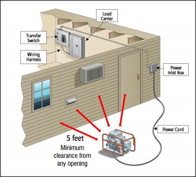
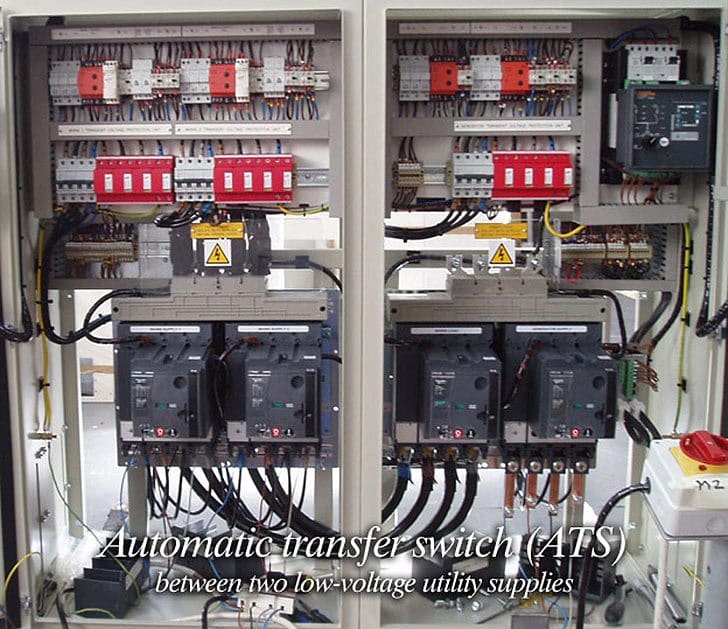
Because the amount of electricity created by a backup generator is not adequate to power all of the electrical circuits in your house youll need to designate a few selected circuits to get backup. Installing a transfer switch refers to the process of adding the necessary trigger to change your energy to generator power in the event of an electrical outage.
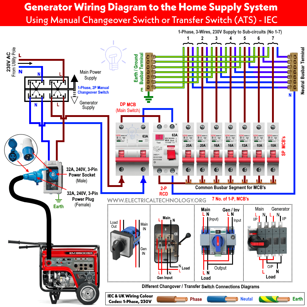
How To Wire Auto Amp Manual Changeover Amp Transfer Switch 1
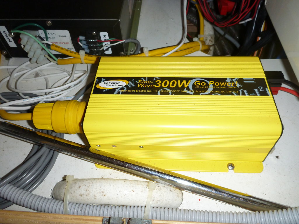
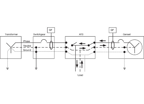
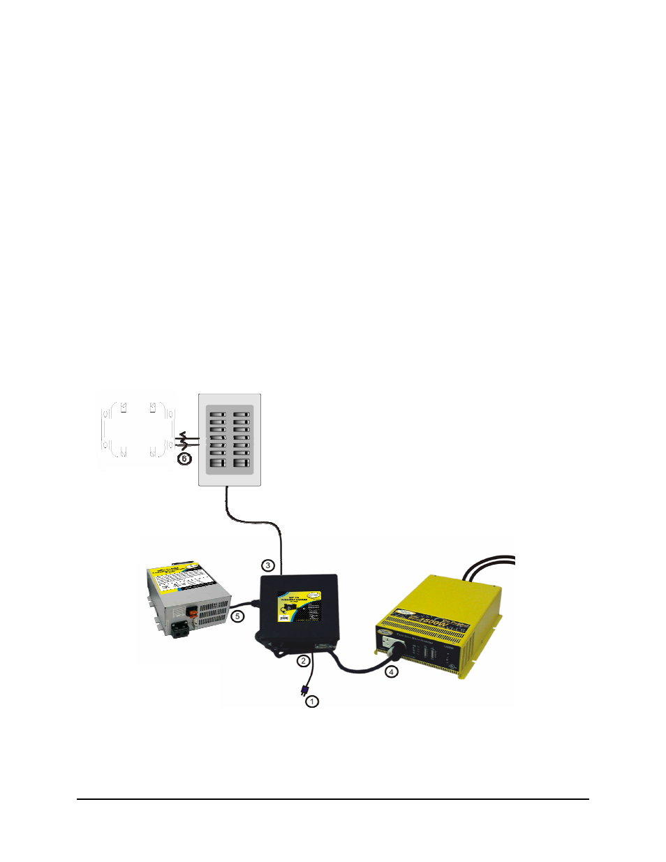
Go power transfer switch wiring diagram. Please right click on the image and save the photo. Of a photo i get via the inverter transfer switch wiring diagram package. This task requires experience with electrical wiring. 800 x 600 px source. Some inverter installations integrate the inverter directly into the ac electrical system. Figure 4 wiring diagram of a manual transfer switch in the off position figure 5 wiring diagram of a manual transfer switch in the on position when utility power is functioning the wires from the circuit breaker in the main electrical distribution panel are connected to the generator sub panel.
Rv battery disconnect switch wiring diagram saleexpert size. Our people also have some more pics related to inverter transfer switch wiring diagram please see the image gallery below click one of the images then the picture. Here are some of the top drawings we receive from various resources we hope these photos will work to you and hopefully very pertinent to just what you desire concerning the inverter transfer switch wiring diagram is. Follow these steps for. This is the 30 amp transfer switch go power. Manual transfer switches require an operator to change the power source while automatic switches detect the loss of power start the back up generator and switch over to the backup power feed.
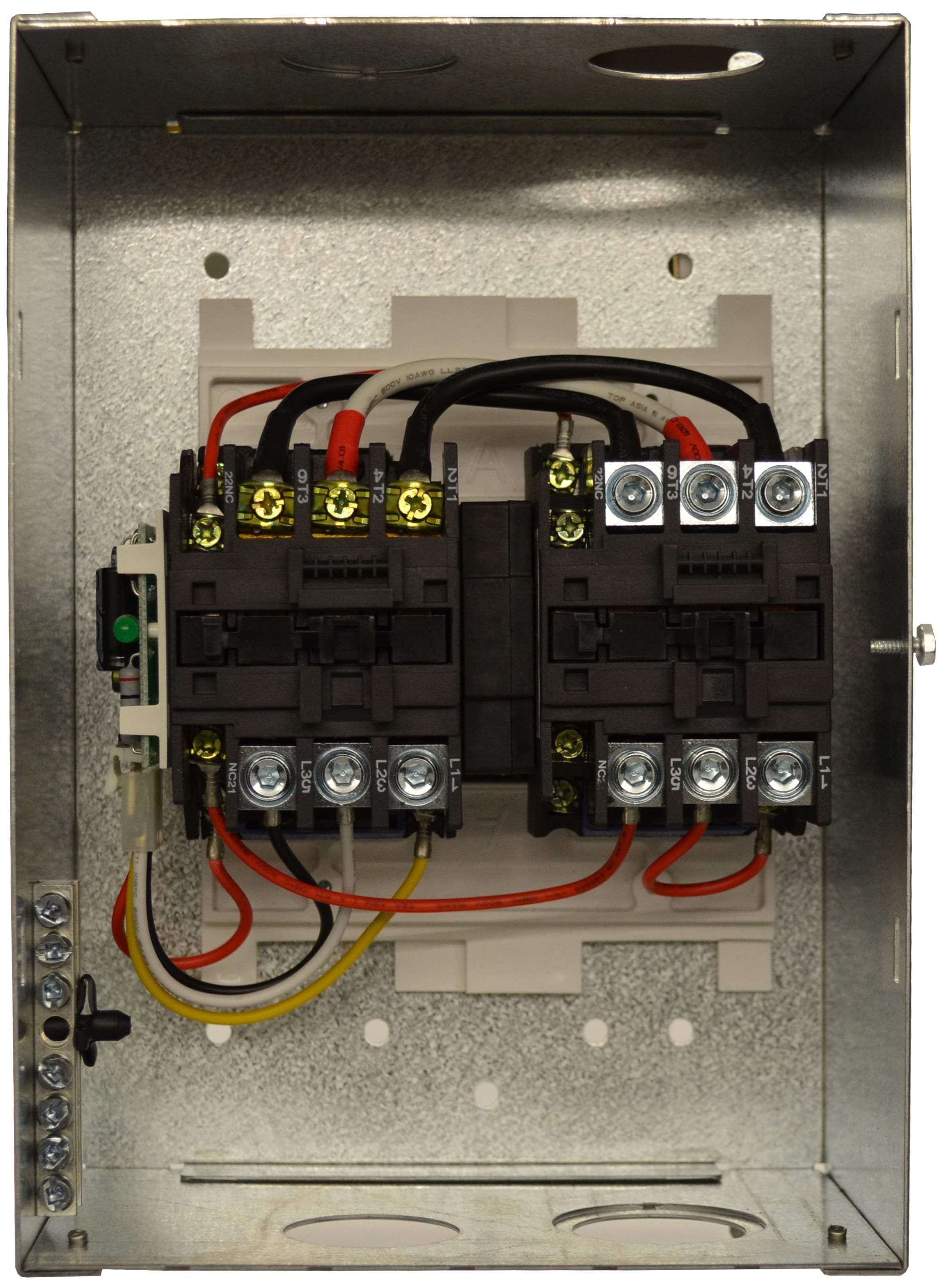
An automatic transfer switch is usually installed to allow both your inverter and shore power to alternatively feed the. Transfer switch 30 amp ts 30 provides automatic power switching between two separate 120 volt ac input sources. You can save this image file to your own personal pc.






.jpg)
