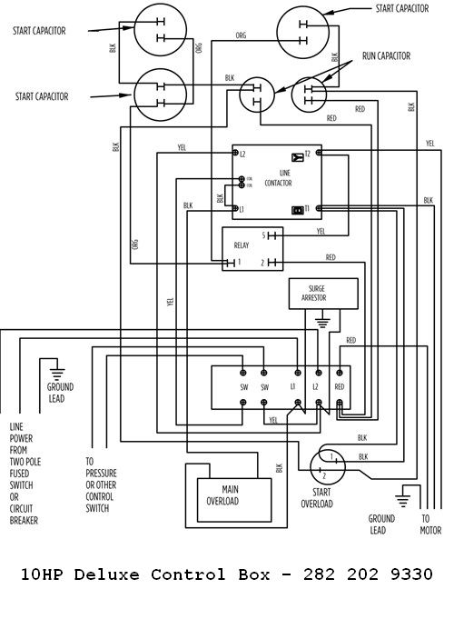
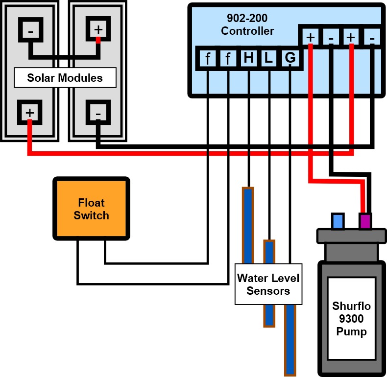
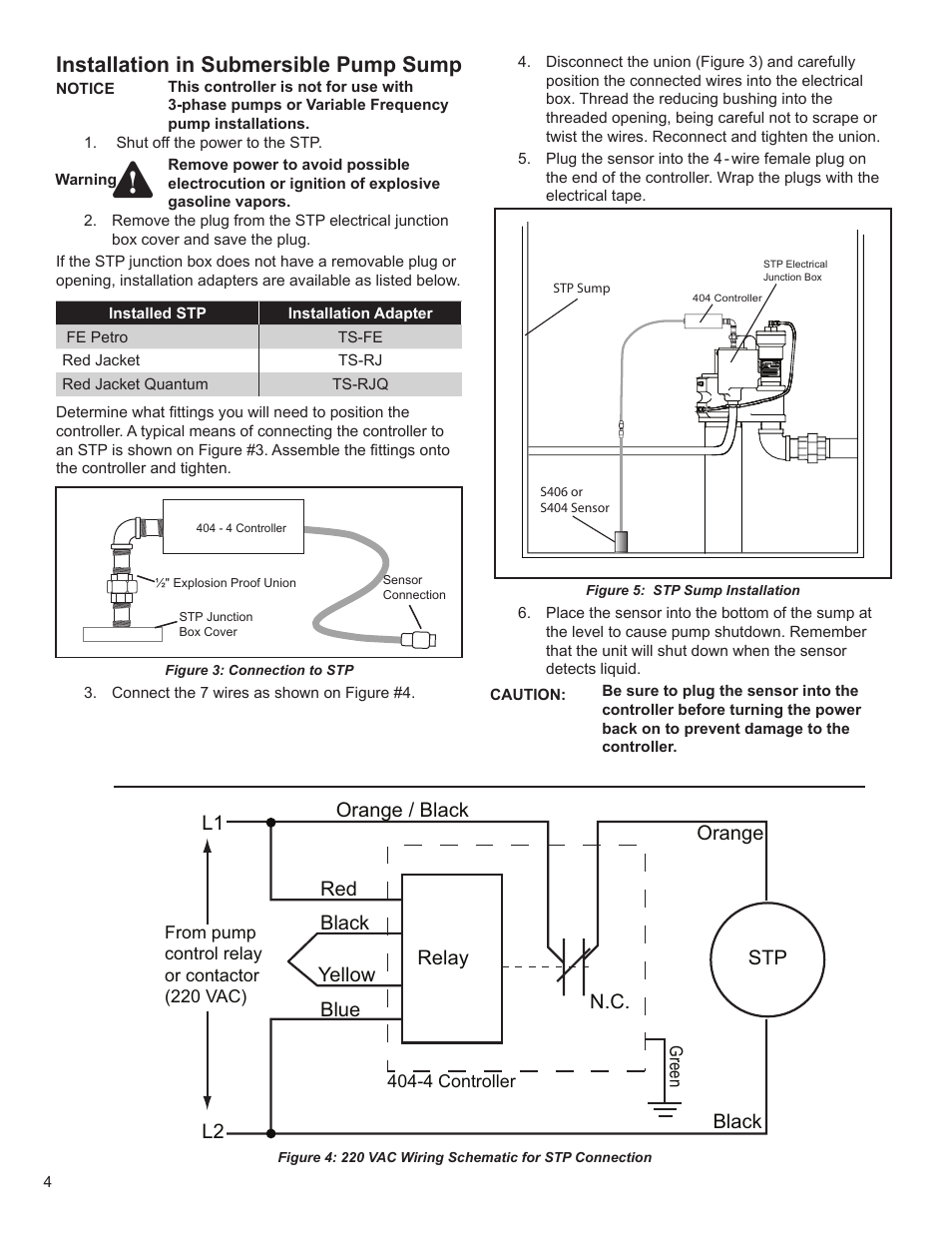
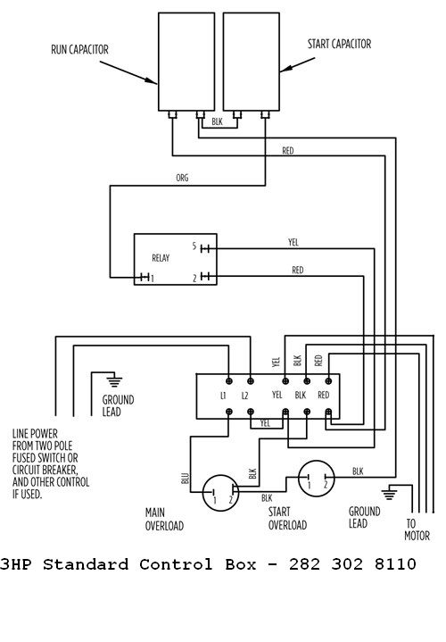
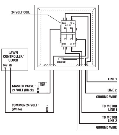
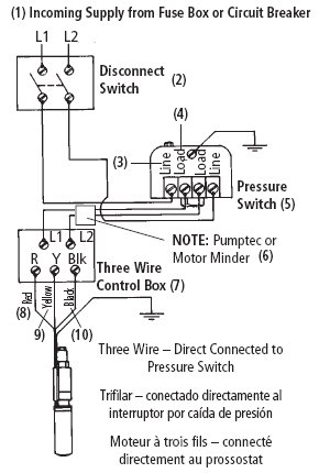
Assortment of 2 wire submersible well pump wiring diagram. Products view all products pump selection find the right pump for your job latest products view our latest products our markets learn about the markets we serve.
Submersible Pumps Submersible Pumps Wiring Diagram
Franklin submersible pump wiring diagram. Franklin electric co inc. During acceleration the pump thrust increases as its output head increases. Enter the model or item number below to search for a specific product. Collection of submersible pump control box wiring diagram. In this video chris shows you how to wire the franklin electric qd control box. Here is the complete guide step by step.
All 3 wire submersible pumps from 13 up to 1 hp utilize a qd control box to start the pump. Assortment of submersible pump wiring diagram. The wiring connection of submersible pump control box is very simple. A wiring diagram is a simplified traditional photographic depiction of an electrical circuit. It shows the parts of the circuit as streamlined shapes and also the power and also signal connections between the devices. It shows the components of the circuit as simplified forms and the power as well as signal connections between the gadgets.
Control box wiring diagrams continued. A wiring diagram is a simplified standard pictorial representation of an electric circuit. Franklin submersible motors are designed primarily for operation in the vertical shaft up position. Single phase submersible pump control box wiring diagram 3 wire submersible pump wiring diagram in submersible pump control box we use a capacitor a resit able thermal overload and dpst switch double pole single throw. It shows the elements of the circuit as streamlined forms and the power and signal connections in between the devices. In cases where the pump head stays below its normal operating range during startup and full speed condition the pump may create upward thrust.
A wiring diagram is a streamlined standard pictorial depiction of an electric circuit.
