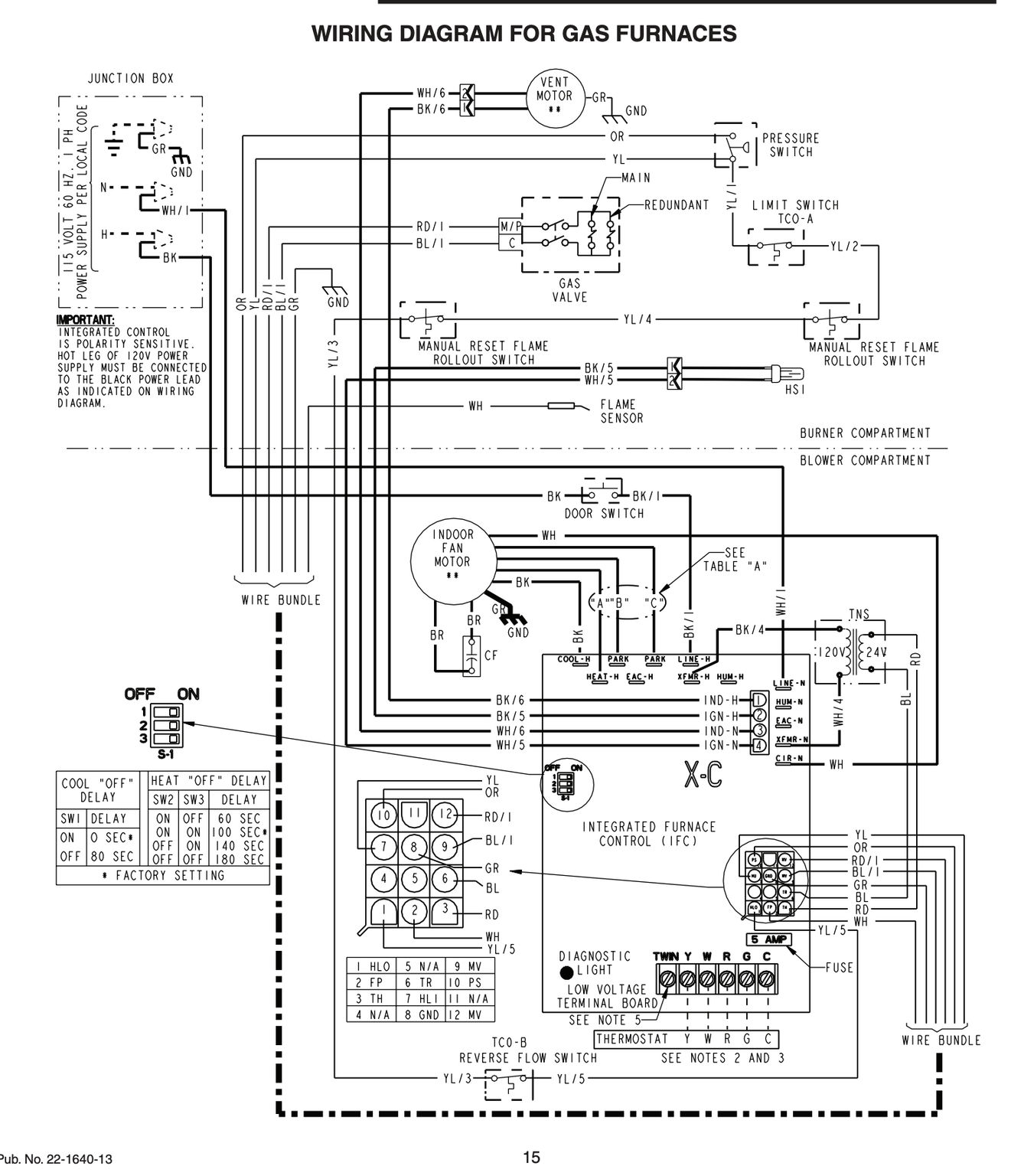
Convenience terminal tied to p22 heat quick connect for factory termination to eh relay if applicable. Dc motor fcu and thermostat wiring details in hindi and urdu.

Fan Coil Unit An Overview Sciencedirect Topics
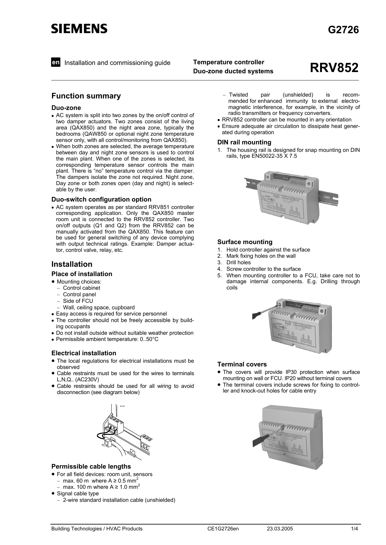
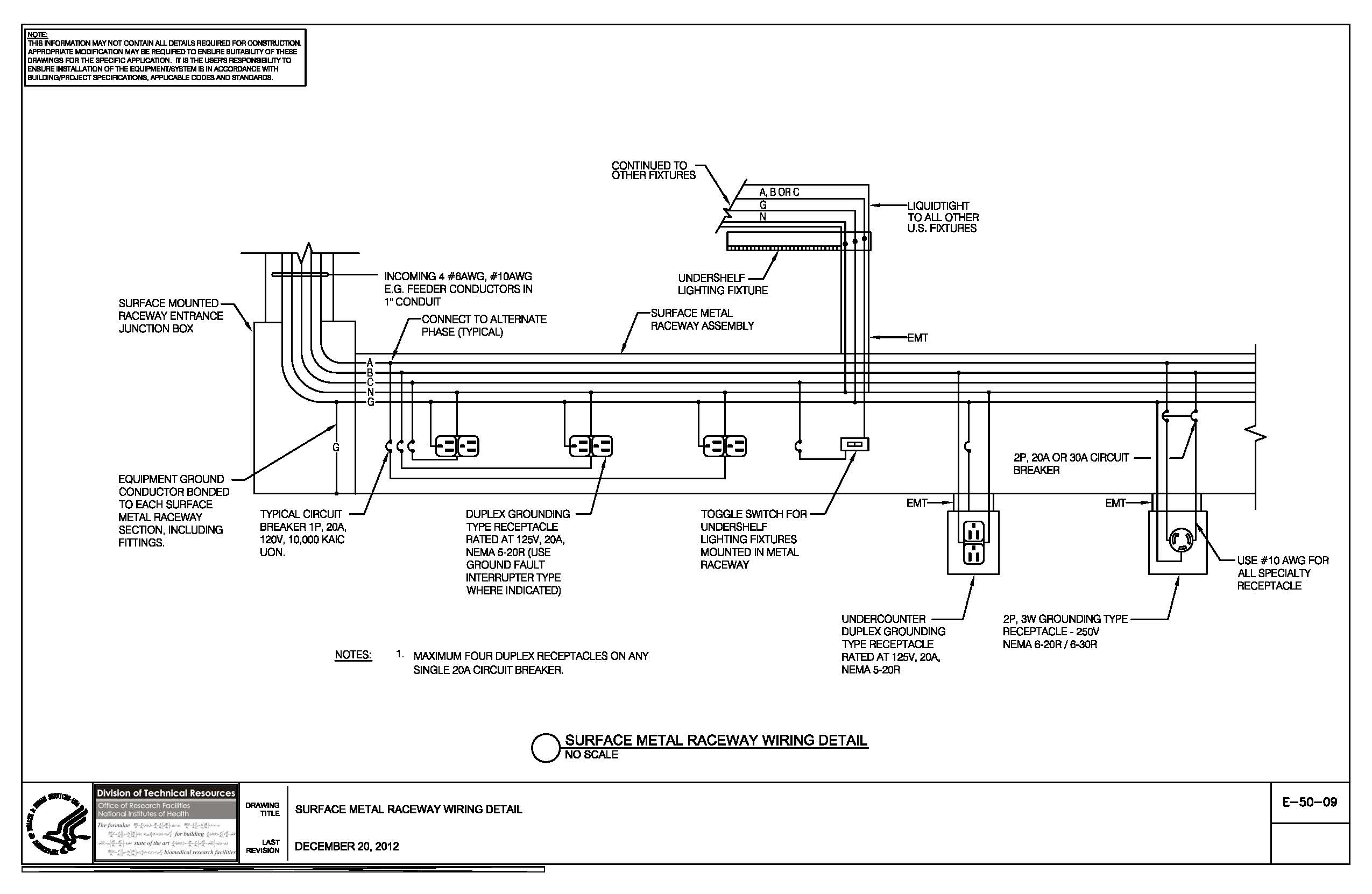
Fcu control panel wiring diagram. Fused connection unit wiring fcu how to wire fused spur duration. Woods 1 scale none job sheet 1 of 13 7 ahu 2 wiring diagram 9 boiler panel 10 boiler panel expansion. Thermostat wiring diagrams for heat pumps heat pump thermostat wire diagrams. L low speed control input for onboard relay. No programming required intuitive interface wiring diagram fcu tpd series thermostat sc series 4 ch relay board rl1com rl1nc rl1. Package ac controll wiring diagram with thermostat rywg wire.
1the mechanical systems control contractor mscc shall be responsible for the selection of providing installing all ddc controllers control devices to accomplish the sequence of. 2 traditional control method of fcu a diagram of a traditional control strategy for a fcu is described in fig. Ll1nl2 nl2 fcu 1 fcu 2 fcu 3 hvlvcvlv hvlvcvlvll1 nl2 nl2 cvlv nl2 3wv 3wv 3wv 3wv 3wv 3wv x1 x2 x3 r s t n 3wv x1x2x3 3 way valve chiller relay 220 240v10a. The control strategy is as follows. Primary drain pan high level sensor hhws 0 fcu control diagram not to scale filter supply fan t occupancy sensor notes. 2 trmspth and trmsptc are room temperature setting values in winter and summer mode respectively.
Fcu traditional valve connection installation time duration. In addition the preloaded interfaces also make it easy for operations in schedule setting temperature compensation and remote control etc. Heat pumps are different than air conditioners because a heat pump uses the process of refrigeration to heat and coolwhile an air conditioner uses the process of refrigeration to only cool the central air conditioner will usually be paired with a gas furnace an electric furnace or some other method of heating. Electrical wiring connection this is a proposed wiring connection. M medium speed control for onboard relay. It may change subject to the chiller unit and must comply with local and national code and regulations.
No rl2 rl3 rl4 rlcom switch ac in gnd vs d d gnd d d vs. W1 tie point for hot water valve actuator or 1s t stage eh control input and thermostat heating output. 11 1 panel blower cover fw series c 12 1 assy auxilliary drain pan 13 1 rack filter fwc series c 14 1 filter 15 1 control enclosure 16 1 control enclosure cover 18 1 assy coil fw 19 1 eh assembly fw series c 20 1 assy outside air fw 21 1 panel toe space wslots fwi series c. 1 control points of the fcu rmsptc fig. 3 fcu wiring 5 ahu flow diagram 6 ahu 1 wiring diagram cover page pittsburgh air systems inc. Siemens wiring an sqs65u actuator with modulating control signal.
Fcu digital controller provided by mscc. Parallels the p15 low quick connect input.

