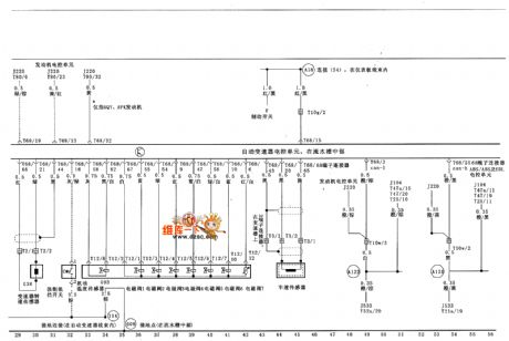
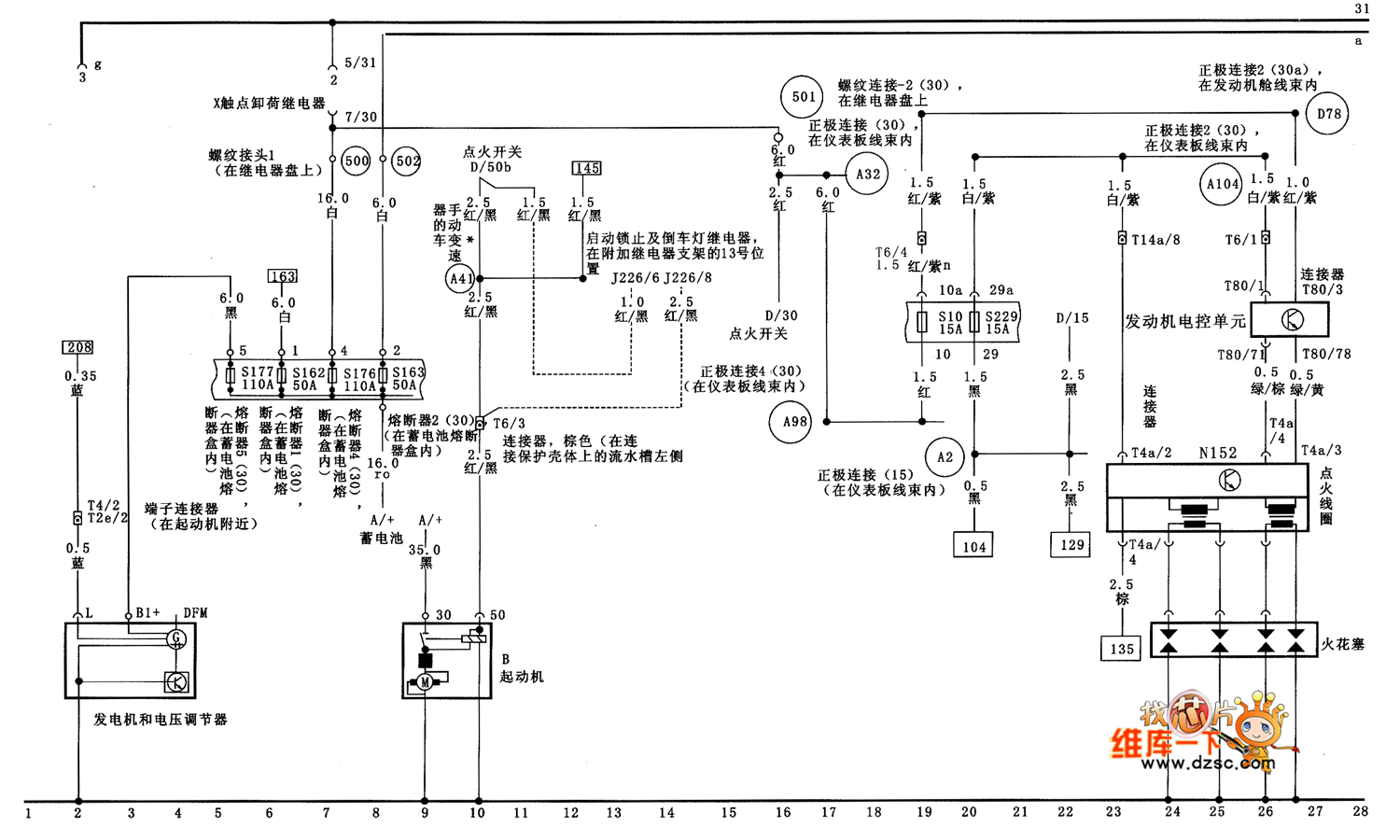
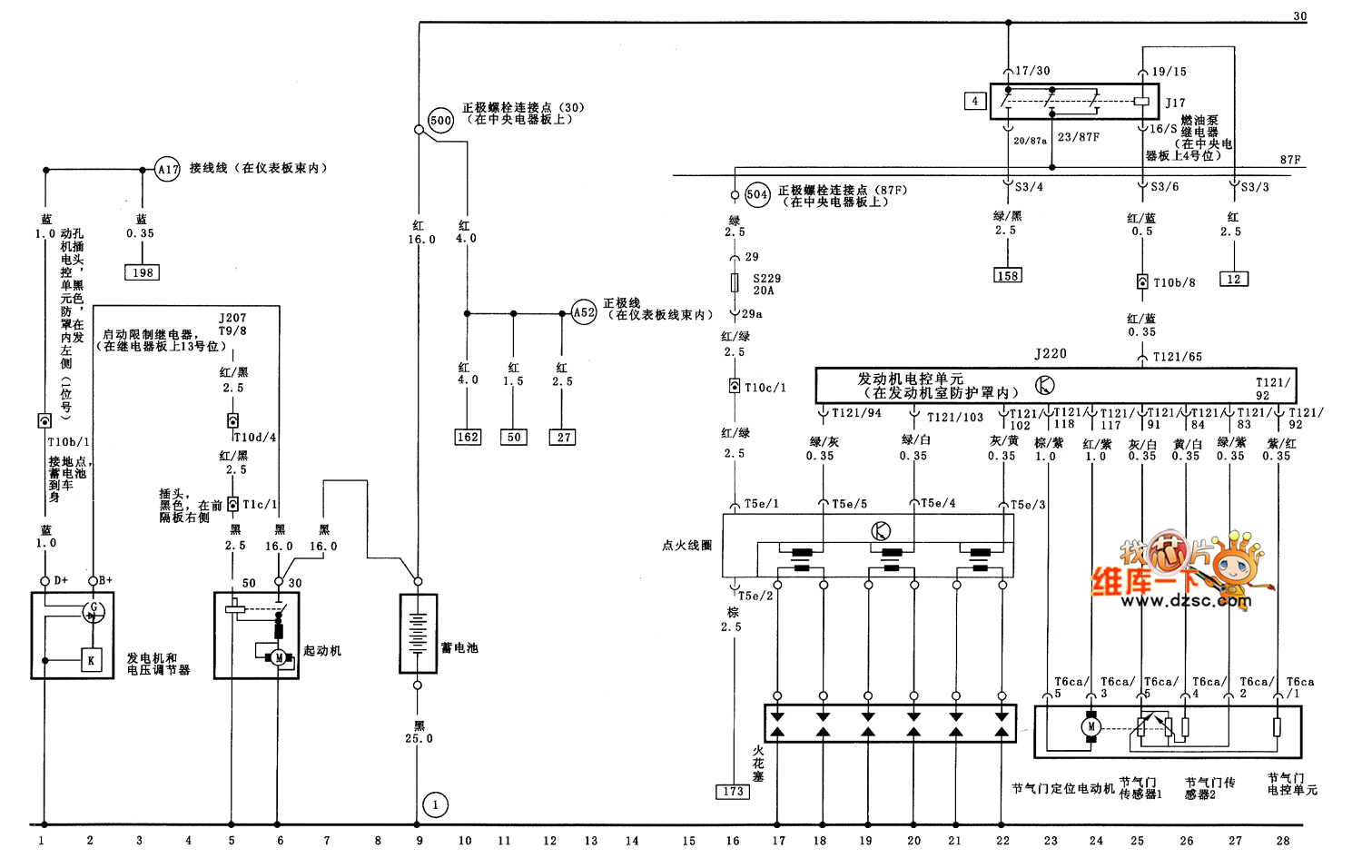
Electronic charging and engine starting circuit diagram there could be third harmonic3f at the neutral point. 1990 toyota supra ma70 fuel system circuit diagram the following circuit diagram shows 1990 toyota supra ma70 fuel system circuit diagram.
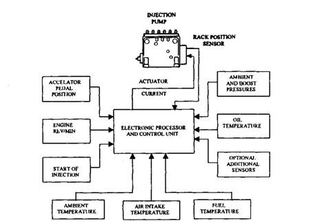
Bosch Electronic Control Automobile
Electronic control unit circuit diagram. Ecuelectronic control unit and its mount location 5. Connect the glow plug wire to the relay contact. There is a fixed drive ratio of. A schematic diagram of an electronic ignition system is shown in figure 236. Build the glow plug control module unit on any general purpose pcb and mount it in a suitable casebox. The fuel system is composed of 3.
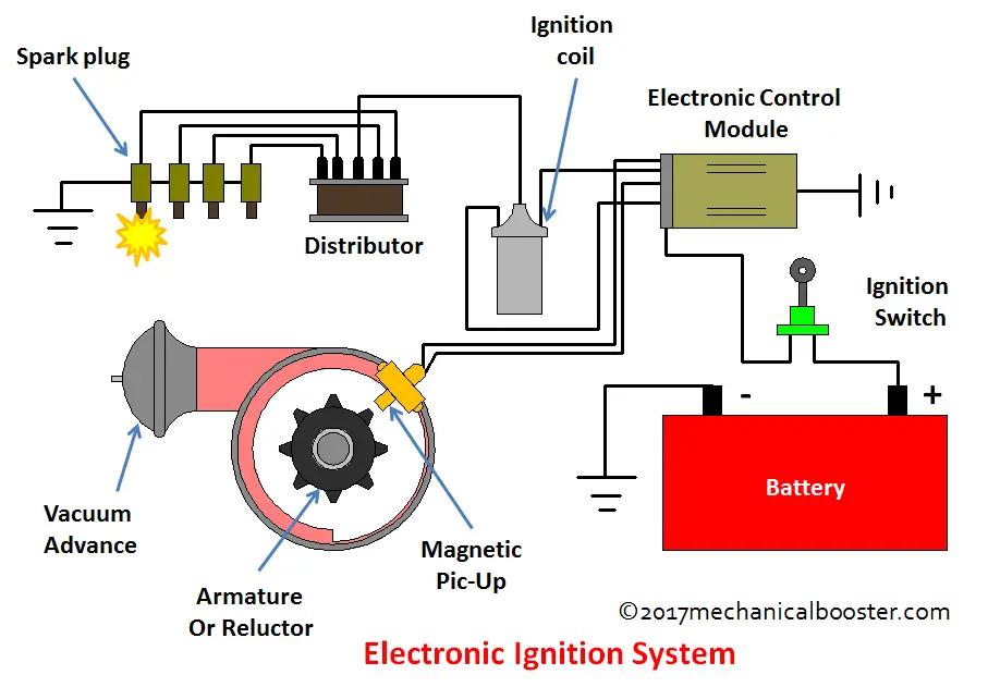
Types of ecu ecm engine control module ebcm electronic brake control module pcm powertrain control module vcm vehicle control module bcm body control module 6. It consists of a battery ignition switch electronic control unit magnetic pick up reluctor or armature ignition coil distributor and spark plugs. Design of electronic control unit ecu for automobiles electronic engine management system m. Project first stage report ee 696. Reading electronic prints diagrams and schematics. The 12v battery source that already available with the vehicle can be used to power the circuit.
Here in this diagram we take the example of the o2 sensor. Each range will cover one third of the tank capacity. To properly read prints and schematics the reader must identify the condition of the components shown and also follow the events that occur as the circuit functions. Construction of electronic ignition system. An electronic control unit ecu is any embedded system in automotive electronics that controls one or more of the electrical systems or subsystems in a vehicle. This is a fairly technical document that has more information than many readers are looking forif you would just like to understand a bit more about how the ecu works and some answers to the more common questions and problems id suggest reading the first three sections then moving on to.
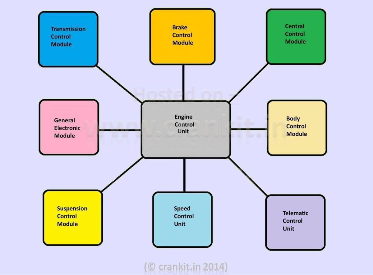
Types of ecu include engine control module ecm powertrain control module pcm transmission control module tcm brake control module bcm or ebcm central control module ccm central timing module ctm general electronic. The very small remote unit is placed near the tank and measures the water level in three ranges by means of two steel rods. Components of ecu an ecu consists of a number of functional blocks. The d jetronic electronic control unit ecu author. Figure 4 comparison of an electronic schematic diagram and its pictorial layout diagram. Hardware design of ecu 7.
As you can see the o2 sensor is connected to the e c m microprocessor inputs on one side and to the ground on the other. Almost empty signaled by means of a red led d3 in the control unit display about half level signaled by means of a yellow led d2 in the control unit display.


