The contacts m will be controlled by the coil mthe output of the motor starter goes to a three phase ac motor. Wiring diagram of single phase distribution board with rcd in nec us iec uk eu electrical wiring color codes double pole mcb dp the isolator or main switch this is the main operating switch which is used to control the electric power supply in the buildings.

Single Phase Switch Distribution Boards Connection Sdb
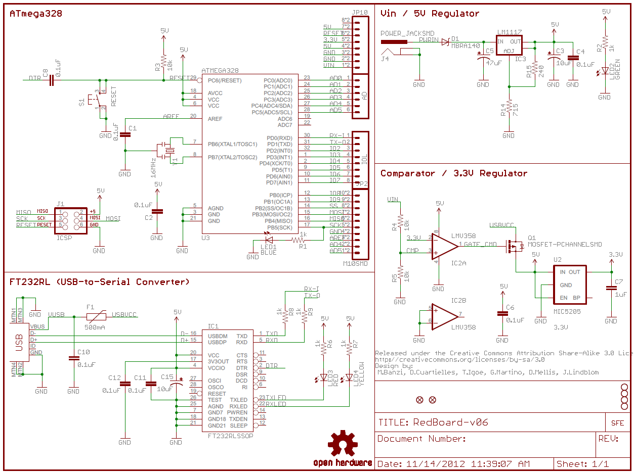
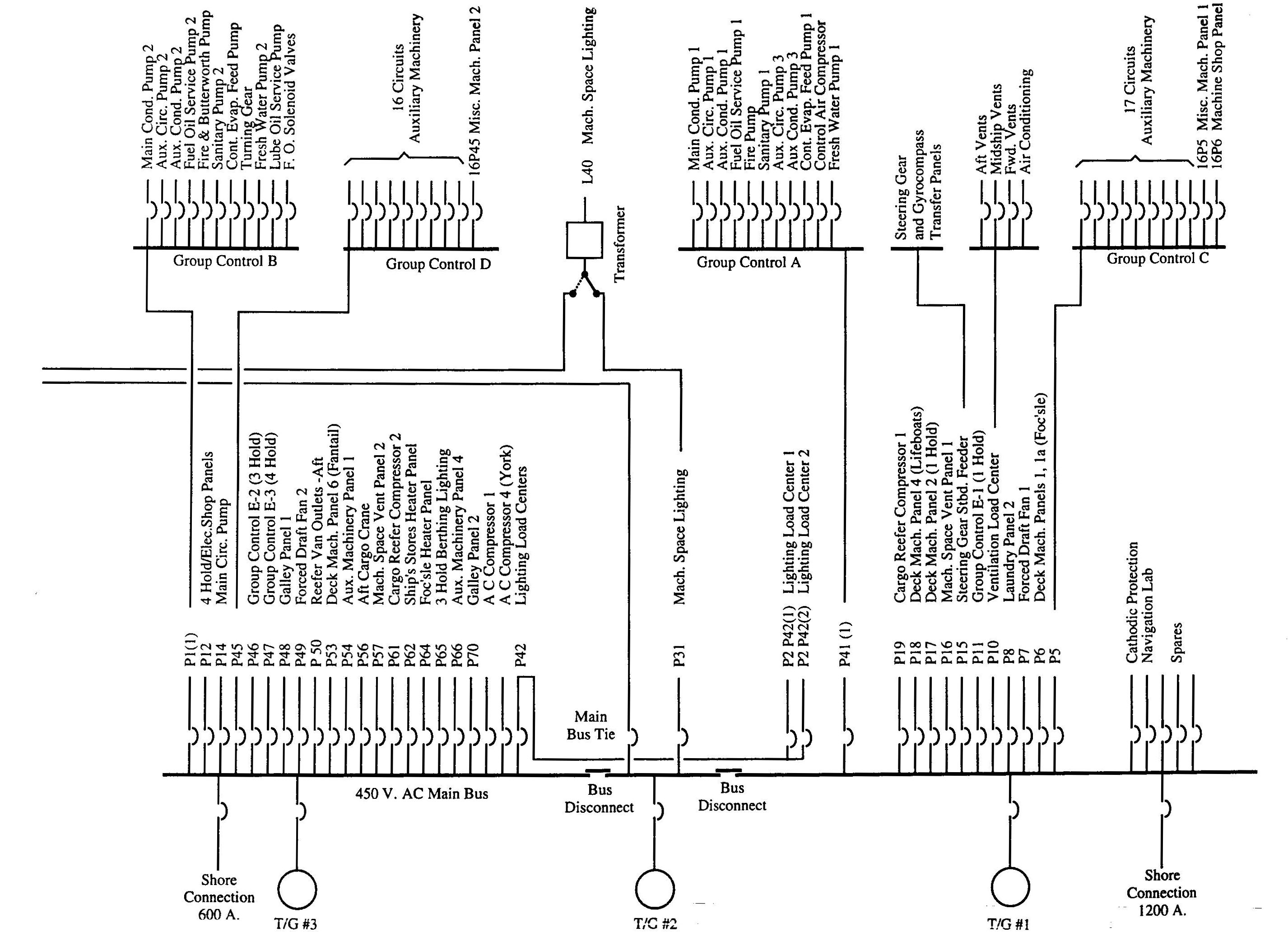
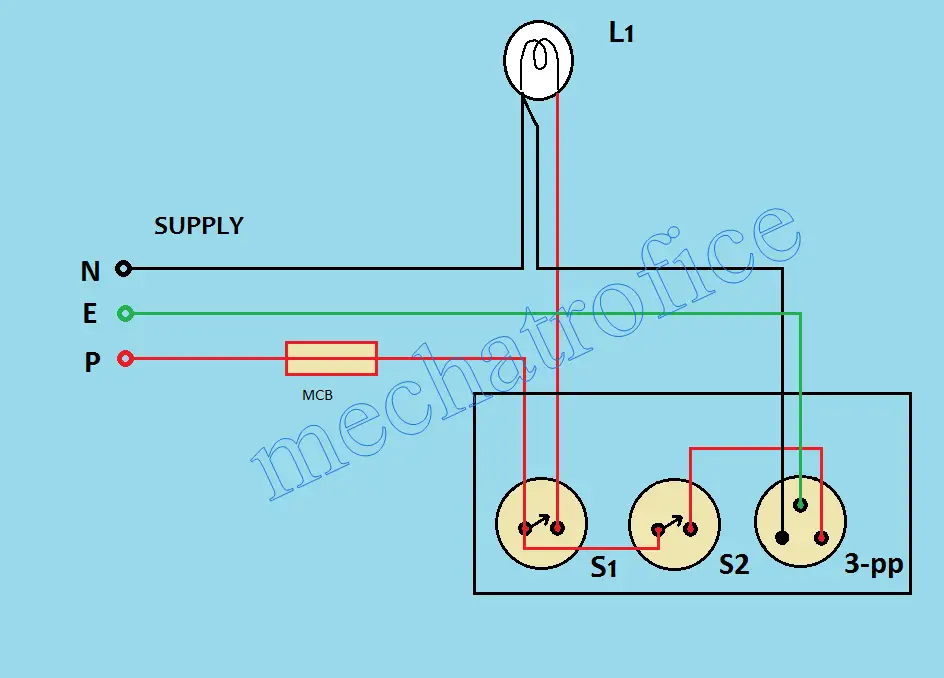
Electrical board connection diagram. Electrical house wiring is the type of electrical work or wiring that we usually do in our homes and offices so basically electric house wiring but if the factory is a factory they are also. The lower voltage is then used to supply power to the left and right rails of the ladder below. How to wire a switch and a load a light bulb to an electrical supply. Electrical connectors connector done his duty very well in e wiring this the easy and compatible way of getting connection or joints in electrical wiring. Figure 1 a motor controller schematic. Designing home wiring layouts.
This is why a good diagram is important for wiring your home accurately and according to electrical codes. This is called advanced connection because this electrical control board is full of complete items which is generally used in our house wiring. In the above diagram i sown electrical cable with its size in mm in which are 6mm or 8mm 4mm 25mm and 15mm electrical cables. Power is supplied by connecting a step down transformer to the control electronics by connecting to phases l2 and l3. Wiring diagrams can be helpful in many ways including illustrated wire colors showing where different elements of your project go using electrical symbols and showing what wire goes where. Keep your diagram nearby.
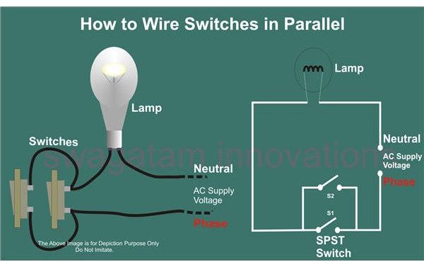
It shows how the electrical wires are interconnected and can also show where fixtures and components may be connected to the system. A wiring diagram is a simple visual representation of the physical connections and physical layout of an electrical system or circuit. As can be seen in the diagram the wiring is pretty simplethe phase is invariably applied to one terminal of the switch the other terminal moves to one of the connections of the load and the other. After learning about the normal connection its time to go for the advance one which includes above missing items. Similarly here is the front view of the arrangement of the items. The following explanation will help you understand better how to design home wiring layouts.
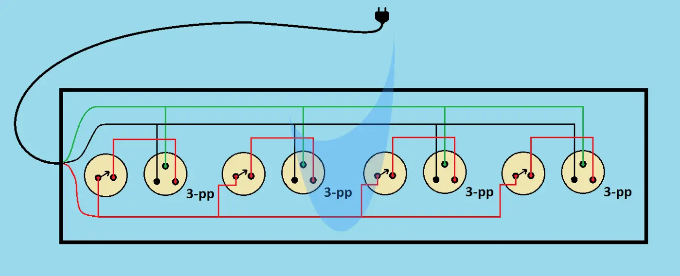
Electric board wiring connection socket switch indicator lampfusefan pointlighting point 7 way board please subscribe my new channel electricalelectronics diagram.


