Which many people have seen the two tone bell sounds from other electronic journals. But they are circuit that made no who apply them since problems three reasons.

Musical Doorbell As A Shadow Sensor Alarm Hack
Doorbell alarm circuit diagram. Circuit diagram and explanation. Above figure shows the circuit diagram for doorbell. Capacitor value can between 22uf to 100uf. This circuit is based on ic um34815a which is a 16 pin musical tone generator ic and this circuit is implemented as 12 tone generator. Using this circuit you can change the old experience of doorbell switching method and can create new hightech method with automatic touch doorbell alarm switch system. Wiring diagram for a two chime doorbell.
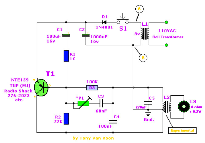
Connect the input wires on the transformer to the source circuit using the black to black white to white and ground to green method. Careful with transistor terminal when constructing the circuit. Song tune 1 song tune 2 etc. This is a 2 tone doorbell circuit which is an electronic buzzer typesbut them has melodic sound than the general electric bell. Wiring for two doors is the same as for one with the transformer hardwired to the 120 volt source from a house circuit. The ic has an in built circuitry to produce ding dong sound each time its pin 3 is pulled low.
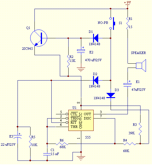
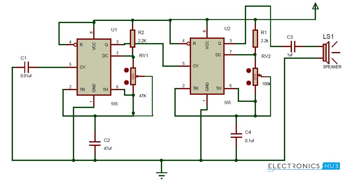
The circuit of 12 tone door bells starts operating as soon as the switch sw 1 is pressed and then the tune is played in an ascending order serially ie. This simple and cost effective ding dong electronic doorbell circuit is based on ic 8021 2. Assemble the circuit as given in fig. Variable resistor rv1 is used to control the ring duration means how long will be the output pin 3 will be high. Here we can see that first 555 timer ic is configured in monostable mode means it will go high and low only once if triggered with trigger pin 2. The sound is stored in the ic as bits as in a rom.


