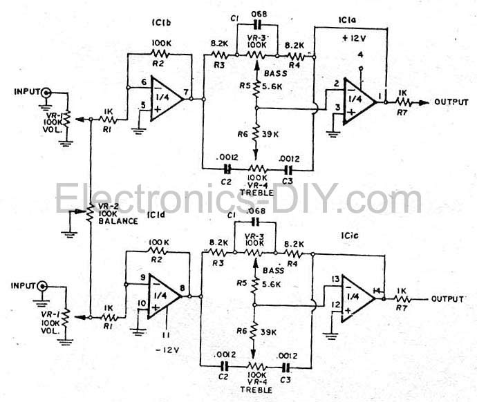
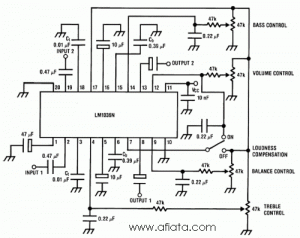
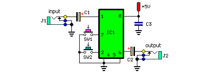
This is a stereo audio tone control circuit which build based on ic lm1036. This is an active stereo tone control circuit using very well known op amp ic of tl072.

Aiyima Tone Bass Treble Volume Control Board 3 Channel
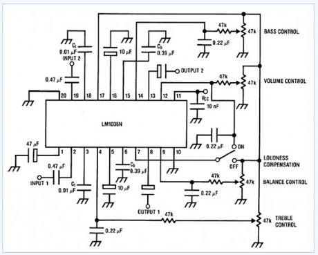
Digital volume bass treble control circuit diagram. Talking about the bass treble circuit it is comparatively much simpler and gainful. Both bass and treble can be boosted or cut and with both controls at their mid positions provides a relatively flat frequency response as illustrated by the blue level response graph line in. One for line stereo one for microphone and has control of the three audio frequency hightreble medium and lowbass. Now i want to suggest you this circuit has 2 forms are. An additional control input allows loudness compensation to be simply effected. This circuit will controll basstreble level tone volume and balance between right channel and left channel input 1 and 2.
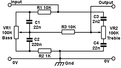
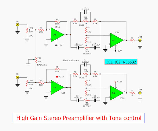
You used to see the passive tone control circuit. In this design we have two inputs. You may use this circuit for stereo applications such as car radio tv and audio systems mp3 player dvd player read more. Then i found this circuit tone control stereo bass treble using two ne5532. Lets take a look at he circuit diagram. Parts list r1 10kω r2 1kω.
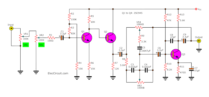
Circuit description of bass treble circuit. The circuit include mic pre amp and mixer control. We have two circuits both transistors op amp as main so smaller but high gain signal. To operate the circuit connect the components as per the circuit diagram give 15v and 15v supply to tl072 opamp and give audio input from mobile by connecting 35 mm audio jack to the circuit. Also it uses an integrated circuit op amp that is low many noises or low noise. Now you can control the bass treble and volume by rotating three potentiometer on the circuit.
And it is a high gain more than two circuits above. My friends want a tone control stereo circuit. Which low quality than active tone control. This circuit can be made without even a veroboard. The lm1036 is a dc controlled tone basstreble volume and balance circuit for stereo applications in car radio tv and audio systems. This is bass treble tone control circuit diagram as ideas.
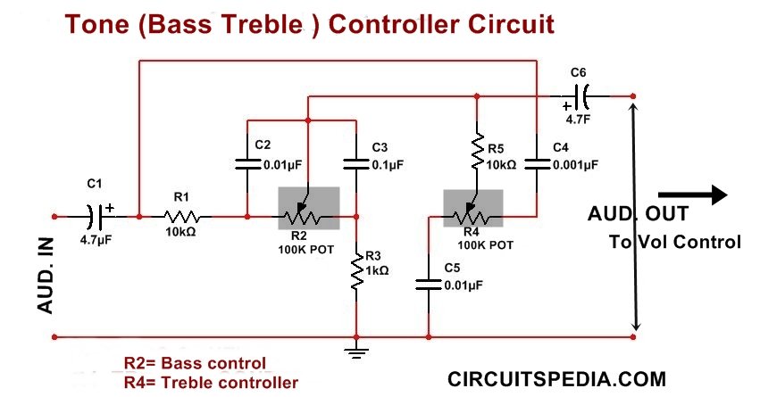
The circuit discussed here is an example of the baxandall tone control circuit illustrated in fig. This low cost bass treble circuit consists of some capacitors resistors and two tc pot for bass and treble control. Resistor r7 gives the isolation between bass and treble. Bass treble tone control circuit bass and treble circuits can be combined to form a two control tone adjust circuit as shown here. It can control the sound bass treble volume well. 422 which is an analogue circuit providing independent control of bass and treble frequencies.
You just solder components as this circuit network is not so complex. The whole bass treble circuit is designed such that it is fit with any stereo systemusing the power supply from the stereo system itself as the total power supply required for this circuit is only 12 volt dc the bass treble circuit is reduced and made more effective. It has only two pin parts.

