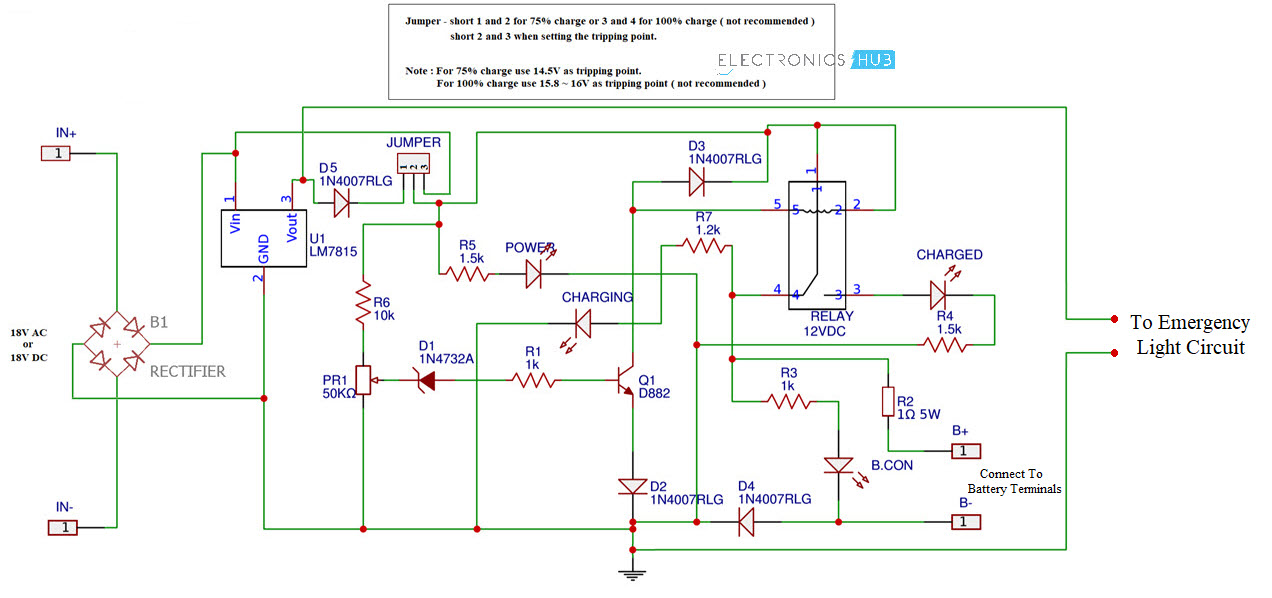
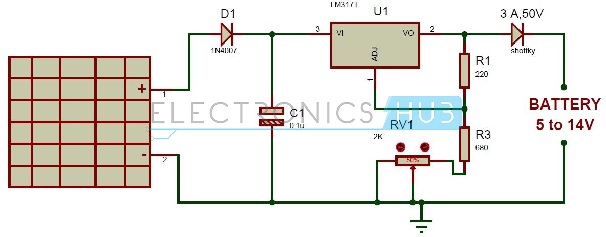
Potentiometer r1 is used to set the. N channel mosfet q2 irf540n is used for charge controlling operation.

Xe 3665 Solar Light Circuit Solar Garden Light Electronic
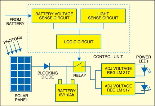
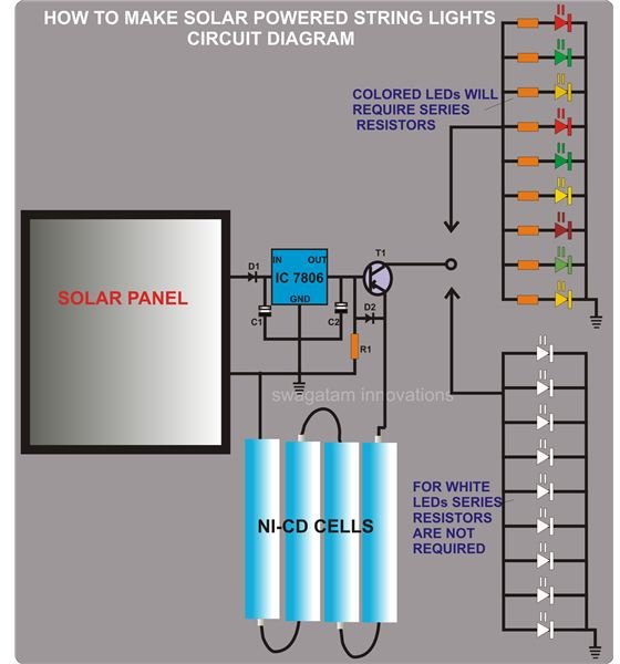
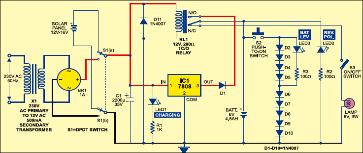
Circuit diagram of solar lighting system. The complete circuit diagram is explained as two parts the first part is given below. Solar cells generate direct current so make sure that dpdt switch s1 is towards the solar panel side. According to the specs of these particular. As can be seen in the given circuit diagram the design basically consists of a solar panel a pnp transistor few leds a battery and a few resistors. Heres a simple small 300 watt solar panel system with a 600 watt dc ac inverter just for an example. The monocrystalline conversion rate is higher than the polycrystalline.
The circuit design is extremely straightforward and may be understood with the following points. One is charging and the other one is to control the leds. The solar garden light circuit will consist of two parts. Capacitor c1 connected in parallel with a 12v relay coil remains charged in daytime until the relay is activated. Solar lighting system circuit. Just a transistor two resistors a diode and the small solar panel and battery pack of your choice.
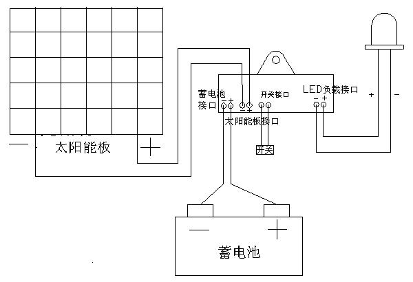
The solar panel or pv cell in the solar street light is one of the most essential parts. Solar garden light circuit diagram. Solar powered led street light with auto intensity control circuit diagram solar panels. A basic solar power system without going into great detail i thought that i would illustrate a very simple and basic solar power system diagram. You could utilize 3 100 watt panels listed below. The value of the two resistors can be changed to suit your.
These cells are available in two types. The solar circuit is super simple. The dc voltage from the solar panel is used to charge the battery and control the relay.

