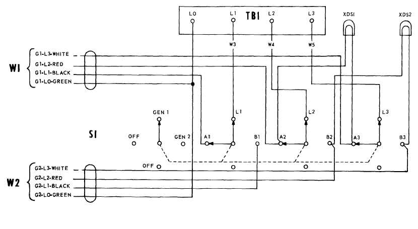
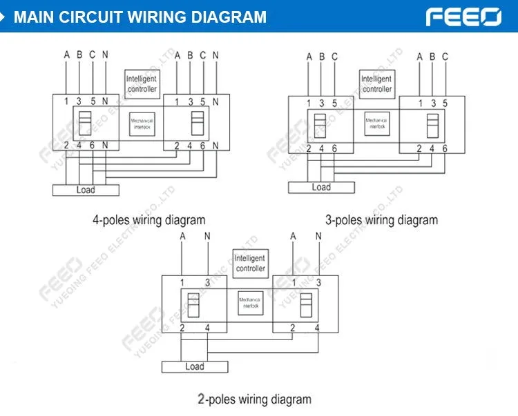
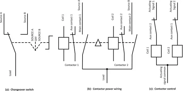
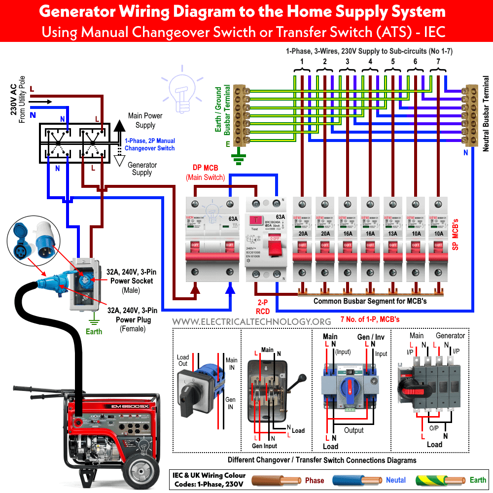
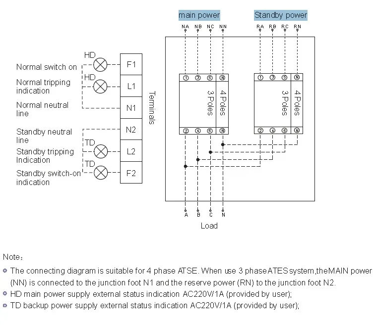
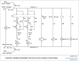
A contactor when closed opens its own auxiliary contact. In fig 2 different connection and wiring diagrams are shown for a two pole single phase manual changeover switch.
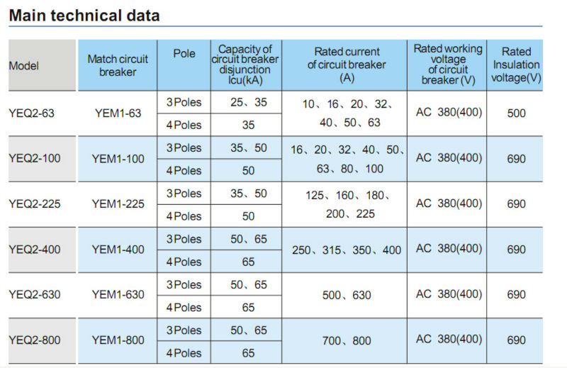
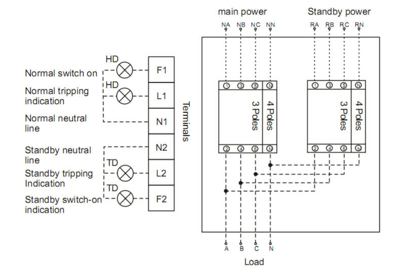
Changeover Wiring Diagram Automatic Changeover Switch For
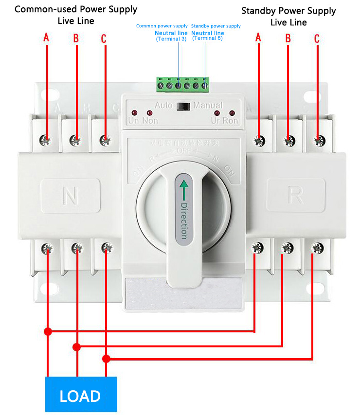
Changeover contactor wiring diagram. The two contactors are joined together with a mechanical interlock mechanism. 40z mains changeover contactor is delivered open without control and power cables and includes. Description factory assembled mains changeover contactors each voa. How to wire a contactor. 6 control wiring single phase sno itemdescription model imaxamps mountingstyle 1 manualchangeover16asinglepolen mco16s 16 panelwallmounted 2 manualchangeover32asinglepolen mco32s 32 panelwallmounted 3 manualchangeover40asinglepolen mco40s 40 panelwallmounted 4 manualchangeover63asinglepolen mco63s 63 panelwall. The upper portion of the changeover switch is directly connected to the main power supply while the lower first and right connections slots are connected to the backup power supply like generator or inverter.
It will not allow to both relays to be in a closed position. Aap sikhenge changeover wiring with diagram automatically changeover in hindi how to wire change over. Many large pieces of equipment are powered directly from high voltage lines. In this automatic changeover switch for generator circuit diagram the contactors of the generator are indicated kg and km. Httpsamznto2hd4acn 8 pin relay. These lines far exceed the 120 volts ac standard in most homes.
For a maximum operating voltage of 1000 v 50 or 60 hz for a switching frequency 600 cyclesh. 240 volts ac and 480 volts ac are commonly used for these large pieces of. According to the block diagram opposite.


