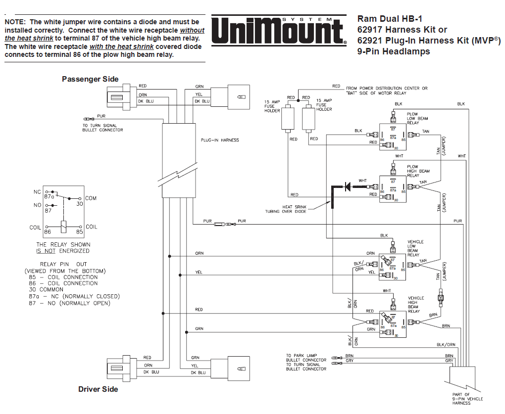
Rt3 wiring diagram rt3 wiring diagram. 11 rt3 power v blade with smarthitch wiring schematic.

Boss Snowplow Parts Diagrams From Iteparts Com
Boss rt3 v plow wiring diagram. The boss snowplow has been carefully designed and built for years of carefree. 8272004 95947 pm. When the plow is mounted on the vehicle. Rt3 v blade manifold wiring diagram 20. Electrical system wiring schematic plow side g10271. When plowing dirt gravel or grass plow shoes should be lowered below the cutting edge surface to prevent the plow from digging into the plowed surface.
10 rt3 v blade msc07679 12 plow shoe assembly steel outer shoe msc01501 12a includes. Microsoft word 13 pin wiring schematicdoc author. When plowing on a solid level area parking lots roads and driveways plow shoes can be raised up to increase cutting edge contact on the plowed surface. 1 quick pin 716 msc01503. Electrical system wiring schematic truck side electrical system wiring schematic truck side g10272. Wiring diagram smartlight2 wiring schematic smartlight2 control plug pin functions.
Recommended vehicle models refer to the boss snowplow application chart and selection guide. Vehicles equipped with air bags are designed such that the air bags will be activated in a frontal collision equivalent to hitting a solid barrier such as a wall at approximately 14 mph or more or.


