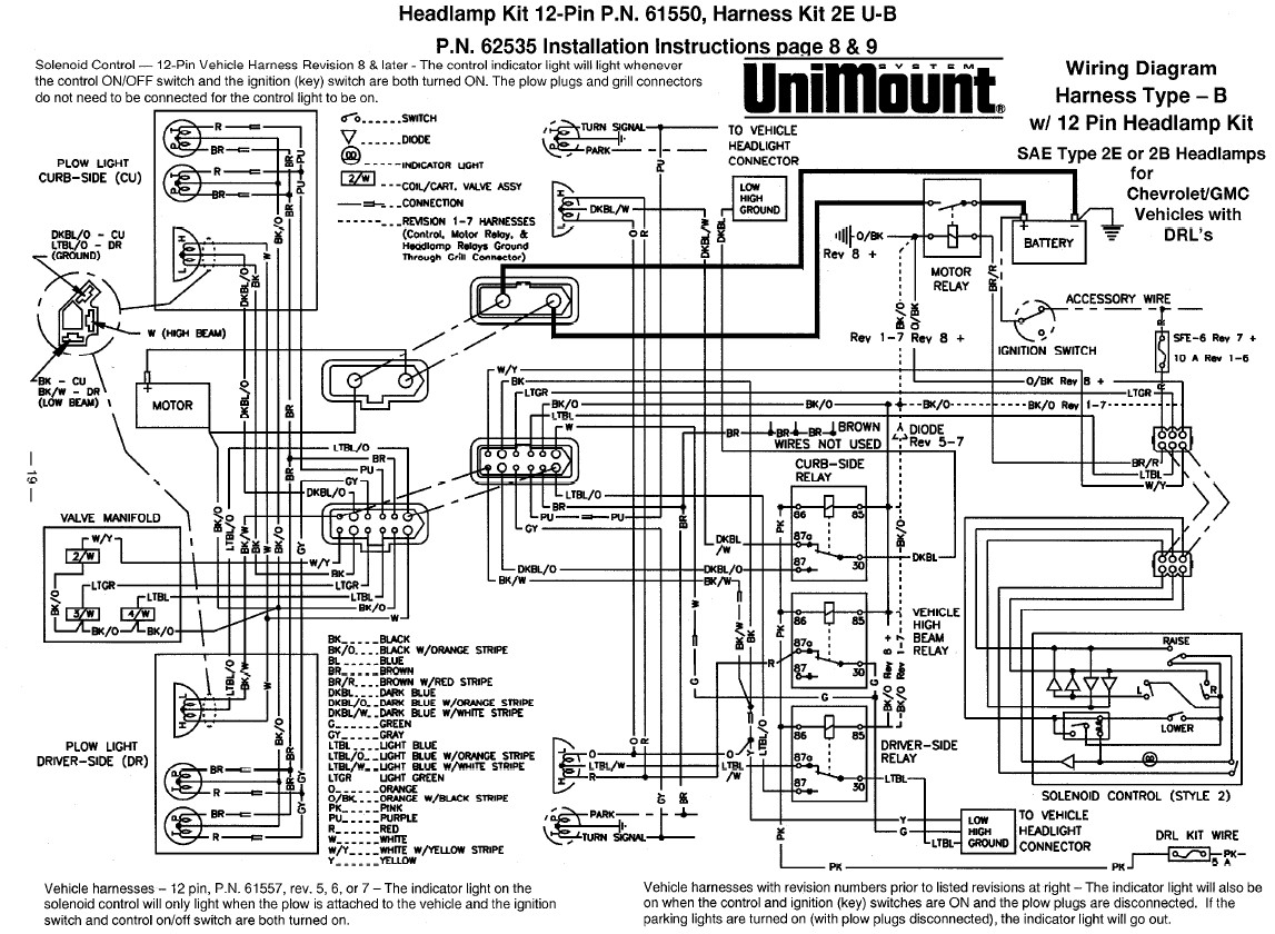
Boss plow controller wiring diagram architectural circuitry diagrams show the approximate areas as well as affiliations of receptacles lighting and long term electrical services in a building. Western mvp3 truck side wiring install on my 2002.

6b932 Wiring Diagram For Gas Furnace Wiring Resources
Boss plow controller wiring diagram. 8272004 95947 pm. A wiring diagram is a streamlined conventional photographic representation of an electric circuit. Boss v plow controller mount. If you have further questions your local boss plow dealer is the person to talk to. Plow review boss vs western snow plow duration. Sometimes wiring diagram may also refer to the architectural wiring program.
They know your plow well and want your complete satisfaction. 4 snowplow operation. Collection of boss v plow wiring diagram. It reveals the parts of the circuit as simplified forms and the power as well as signal links in between the gadgets. It shows the elements of the circuit as streamlined forms as well as the power and signal links between the devices. Microsoft word 13 pin wiring schematicdoc author.
Electrical system wiring schematic truck side electrical system wiring schematic truck side g10272. Adjoining cord courses may be revealed about where particular receptacles or components have to be on a common circuit. Western unimount diy controller part 1. Microsoft word joystick wiring schematic str bladedoc. Working on it 46871 views. Straight blade harness wiring diagram g10074 color function pin black 12 volts 1 orange plow down 2 white plow up 3 red right 4 green left 5 blue left 6 yellow right 7 purple pump solenoid 8 brown ground 9.
11 rt3 power v blade with smarthitch wiring schematic figure 6. Rt3 wiring diagram rt3 wiring diagram. Variety of boss plow controller wiring diagram. Electrical system wiring schematic plow side g10271. Rt3 power v blade with smarthitch wiring diagram figure 5. The wiring diagram on the opposite hand is particularly beneficial to an outside electrician.
Wiring diagram smartlight2 wiring schematic smartlight2 control plug pin functions. A wiring diagram is a simplified standard photographic depiction of an electrical circuit. The simplest approach to read a home wiring diagram is to begin at the source or the major power supply.


