Although we can control the lighting density by using a light dimmer switch with led lamps or pwm controller with led. Hi i have just bought salvaged servants bell box indicator but need help with wiring.

Complete Circuit Diagram Of An Automatic School Bell
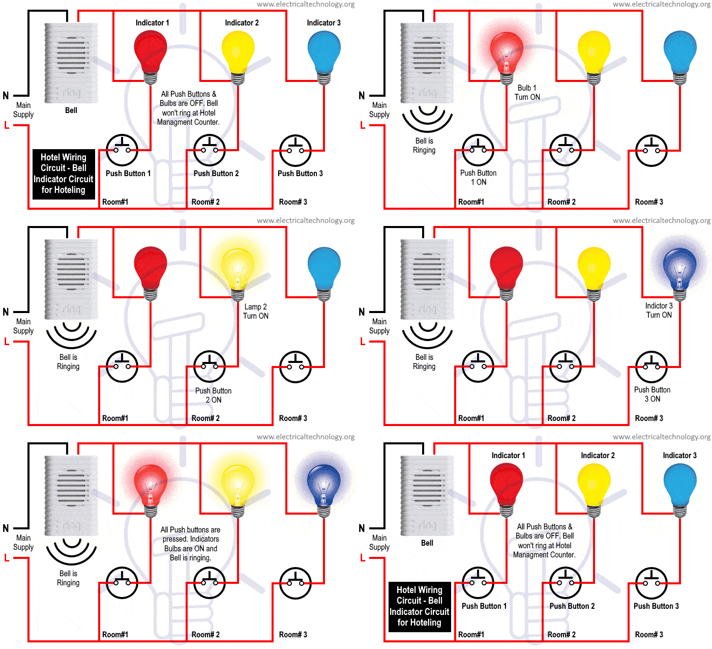
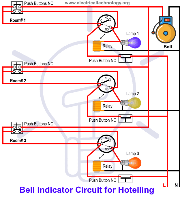
Bell indicator wiring diagram. Project fire 39442 views. Bell bsp wiring diagram. Bell bstl 801 with a fail safe lock wiring diagrams. When a guest presses the push button the specified indicator with room number starts to glow with ringing bell at the hotel management and attendant panel. Engine running verify the low coolant indicator turns off. Bell bstl 719s wiring diagrams.
If you are uncomfortable reading wiring diagrams hooking up wires or soldering them in place consult a licensed electrician for assistance or use the built in rechargeable battery to power your video doorbell. It is similar to the one in crts post 29 may 07. Wiring diagram for a two chime doorbell. How to connect doorbell wires doorbell wiring diagram tutorial doorbell wiring 4 wires doorbell connection in hindi calling bell switch house calling. How to wire a potter vsr flow switch to a bell duration. The clapper hits the bell and makes it ring.
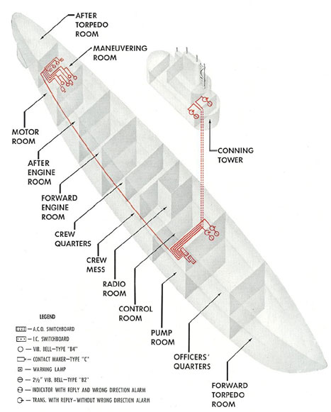
Hostel wiring circuit diagram and working it can be used to find the exact location and room where the guest needs attendant help. Bell bstl 902 10 vrk2 10 bl2 12 multi way systems pd 042 iss 5 bell bstl 901 vrk1 bl1 1 way systems pd 151 iss1 bell bstl 2 panel 1 entrance ac wiring with 59s pd 138. Servants bell box indicator wiring. 8 nov 2007 messages. If the indicator turns off test the ground circuit for an openhigh resistance. If all circuits test normal replace the coolant level switch.
Connecting the ring video doorbell 2 to an ac transformer requires some knowledge of wiring and soldering. Discussion in electrics uk started by delbert 8 nov 2007. Potter signal 73982 views. Wiring a zonecheck addressable flow switch duration. If the indicator does not turn off test the signal circuit for an openhigh resistance. Bell bstl 801 cabling for dc systems upto 10 way.
You can see that a door bell normally has two wires which needs mains supply voltage to operate the bell switch also has two terminals and functions as a cut off system and stops the flow of. The door bell shown in the diagram can be replaced by either a fan light or any other appliance to get the particular relevant wiring completed. We call it hospital wiring circuit by using only switches and lamps to control the lighting density of bulbs in a room especially for admitted patients in the hospital. Connect the input wires on the transformer to the source circuit using the black to black white to white and ground to green method. Wiring for two doors is the same as for one with the transformer hardwired to the 120 volt source from a house circuit. Light control circuit by switches for patient in hospital rooms.




.jpg)


