Electric power single and three phase power active reactive apparent. Everything about basic electrical engineering.

Basic Electrical Diagram Electrical Plan Solutions
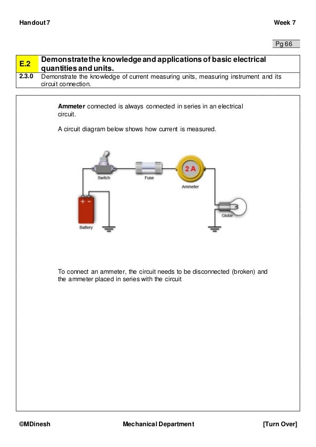
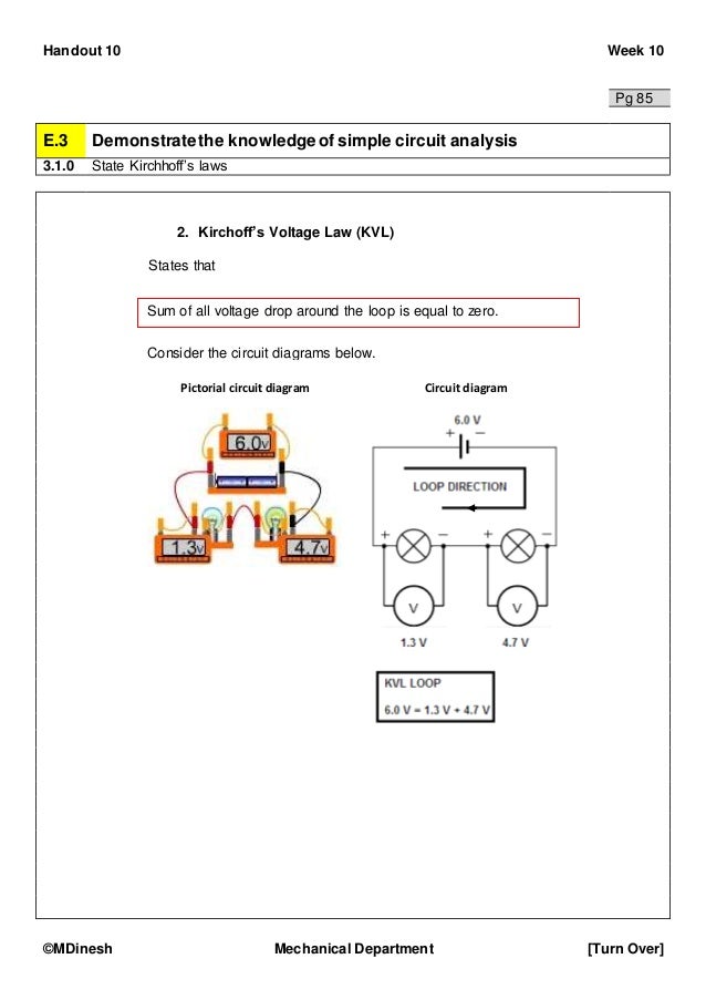
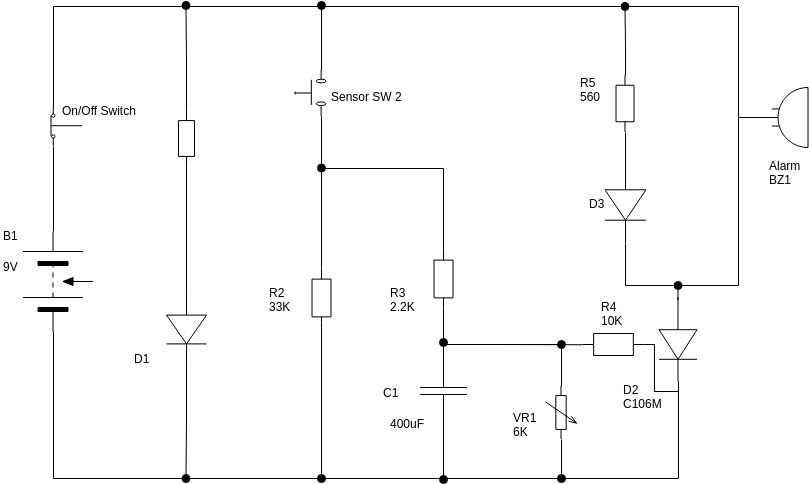
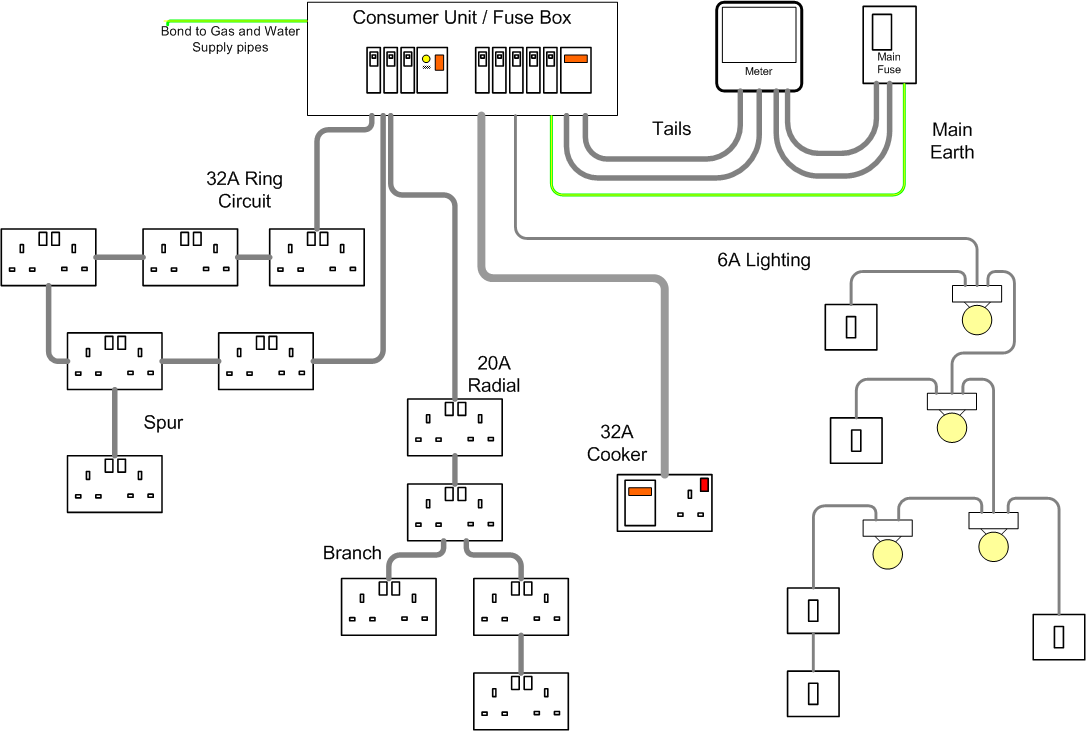
Basic electrical diagram. An electric circuit is a closed loop with a continuous flow of electric current from the power supply to the load. Choose from the list below to navigate to various rooms of this home. Basic home wiring diagrams fully explained home electrical wiring diagrams with pictures including an actual set of house plans that i used to wire a new home. Lets take a look at how to use the basic electrical symbols to draw a schematic diagram of the circuit and its components. There are three d cells placed in a battery pack to power a circuit containing three light bulbs. We explain concepts like electricity resistance voltage inductors capacitors electromagnetism and more.
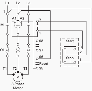
Mapping out an electrical network can be easily done using a quality electrical diagram software like visual paradigm online. Basic electrical home wiring diagrams tutorials ups inverter wiring diagrams connection solar panel wiring installation diagrams batteries wiring connections and diagrams single phase three phase wiring diagrams 1 phase 3 phase wiringthree phase motor power control wiring diagrams. We know that electric current flows in a closed. A basic electrical circuit diagram is a simplified schematic representation of an electric circuit. The resistor symbol. Daily life on the earth is nearly impossible without electricity.
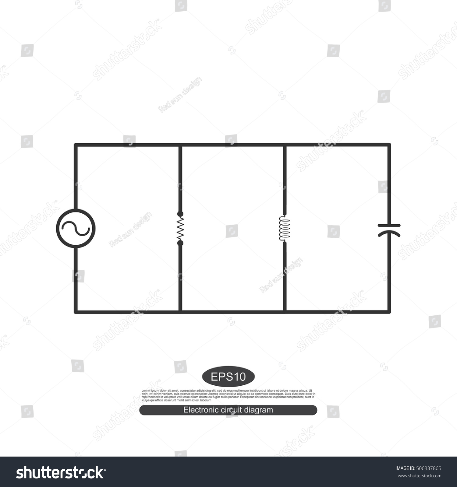
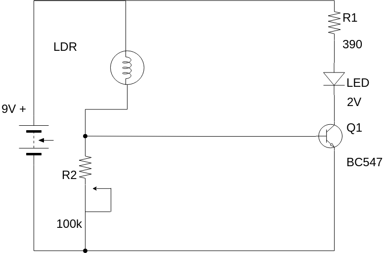
Electric circuits like ac lighting circuit battery charging circuit energy meter switch circuit air conditioning circuit thermocouple circuit dc lighting circuit multimeter circuit current transformer. A basic electrical diagram is a graphical representation of simple electrical circuit. Here are ten simple electric circuits commonly found around the home. It uses standard electrical symbols for the components in the circuit and does not show the physical arrangements of the components. Some most commonly used basic electrical symbols in schematic diagrams are shown below. December 29 2018 june 8 2019.
It shows the components and interconnections of the circuit using standardized symbols. How to draw a basic electrical diagram.
