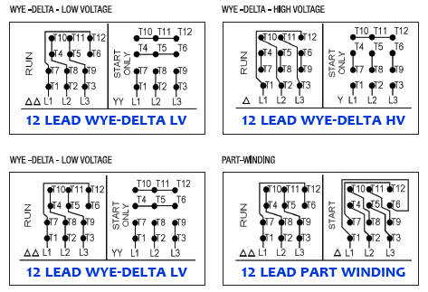
Waynes garage 5517 views. Each type of baldor electric motor has labeled wiring diagrams on a plate fixed on the motor.
Wiring Diagram For 12 Lead 480 Volt Motor Wiring Diagram Source
Baldor motor wiring diagrams 3 phase 480v. Single phase motor wiring diagram with capacitor baldor single phase motor wiring diagram with capacitor single phase fan motor wiring diagram with capacitor single phase motor connection diagram with capacitor every electrical arrangement is made up of various unique pieces. Baldor motor wiring diagram baldor 5hp motor wiring diagram baldor brake motor wiring diagram baldor dc motor wiring diagram every electrical structure is composed of various diverse parts. 3 phase motor starter wiring diagram manual schematic wonderful 208 baldor motor wiring diagram. Baldor weg leeson duration. Wiring diagram also gives useful recommendations for projects that might need some additional equipment. This e book even includes ideas for extra supplies that you might require as a way to finish your assignments.
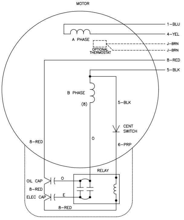
If not the arrangement will not function as it should be. Wiring connect the motor as shown in the connection diagrams. Each component ought to be placed and linked to different parts in particular manner. The wiring fusing and grounding must comply with the national electrical code. Baldor produces a wide range of alternating current ac and direct current dc electric motors in 26 plants world wide. Customer acknowledges and agrees that for abb software or for abb services comprised of data information analyses estimates output or models collectively information such information is based upon customers data.
Yet with the help of this step by step guide this task will be become as easy as counting to five. Now for the purposes of safety the steps listed below will only demonstrate how to wire a motor for 240v. Thank you for your time and. How to wire 3 phase motor to 240 volt system step by step duration. Refer to mn408 for additional details on lead marking. Wiring a baldor motor can at first glance look to be a very intimidating task.
Thank you for watching my channel. Single phase electric motor wiring tutorial. All the videos i upload is to assist any individual with some thing they might of not know until watching one of these videos. Capacitor motor single phase wiring diagrams always use wiring diagram supplied on motor nameplate. W2 cj2 ui vi wi w2 cj2 ui vi wi a cow voltage y high voltage z t4 til t12 10 til t4 t5 ali l2 t12 ti blu t2 wht t3org t4 yel t5 blk t6 gry t7 pnk t8 red t9 brk red tio curry tii grn t12 vlt z t4 til t12. If this motor is installed as part of a motor control drive system connect and protect the motor according to the control manufacturers diagrams.
Each component should be set and connected with different parts in particular way.


