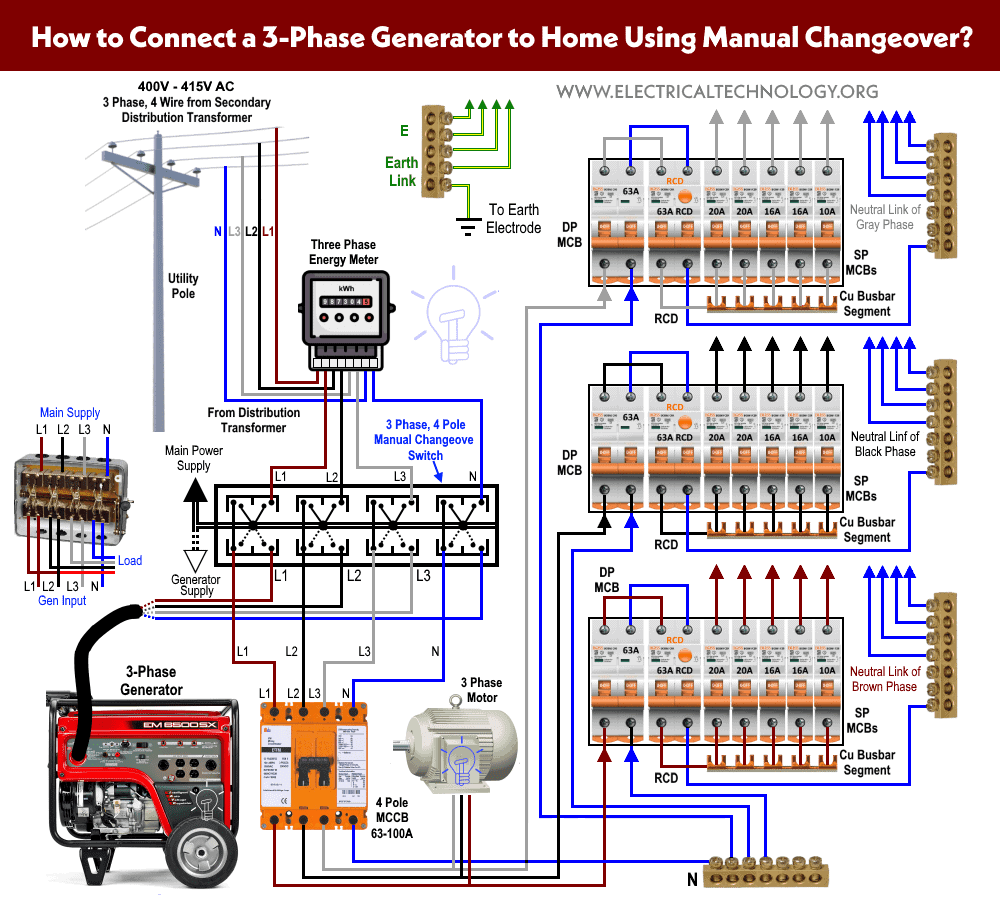
The circuit operation commences once the switch s1 is at any of its position. This post i will shown the complete method of manual or handle change over switch the knob type manual changeover switch wiring same like handle change over switch and its just like a voltmeter sector switch.

Automatic Changeover Switch Using Ic Envirementalb Com
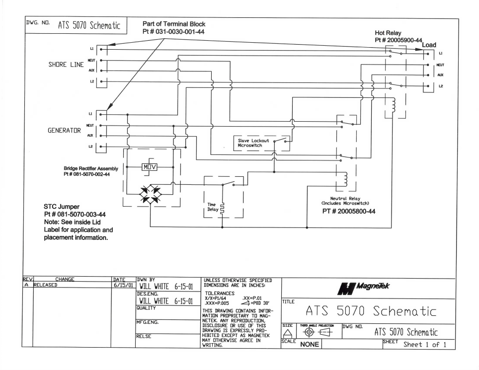
Auto changeover switch circuit diagram. In this video you will find out how to use phase failure relay in simple auto changeover application. This could be used for switching over the output from ac mains to inverter mains during inappropriate voltage conditions. A smart way to build an automatic changeover switch is by using a motorized changeover together with be28 ats controller. When there is a power failure on mains 1 the pfr will open. In this automatic changeover switch for generator circuit diagram the contactors of the generator are indicated kg and km. Internally this reset pin is the reset pin of the sr flip flop and hence the output of 555 timer is a low logic signal.
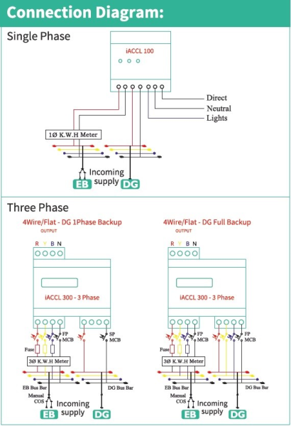
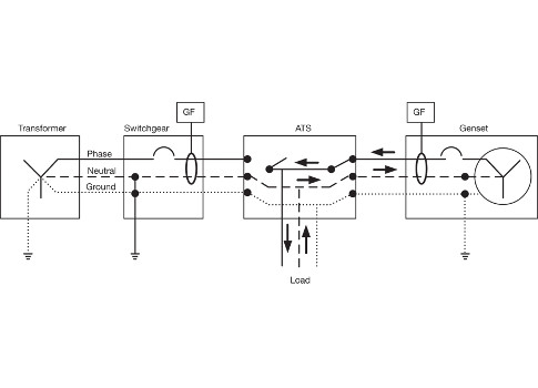
Automatic changeover switch for generator circuit diagram. It is also shows the working and operation for different changeover switches wiring connections like single phase manual changeover switch with generator three phase manual transfer switch connection with generator as well as single phase and three phase automatic transfer switches connections to the 1 and 3 phase generators and main fuse board. This circuit can be used for the automatic switchover of a load between a battery and a wall adapterltc4412 controls an external p channel mosfet to create a near ideal diode function for power switch over and load sharing. Automatic changeover circuit operation. The circuit diagram shown here is of a automatic changeover switch using ic ltc4412 from linear technologies. Compatible with abb eaton socomec motorized transfer switches.
Ups relay changeover circuit. What is an automatic transfer switch and how does it work. In today ups inverter installation tutorial we will show how to connect and install the battery backup power through. The idea of the system is simple. A contactor when closed opens its own auxiliary contact. The explained circuit will effectively switch the connected appliances to the generator mains during power failure however it wont be able to switch start the generator automatically this will need to be done manually because most generators involve a difficult mechanical actuation procedure.
Manual changeover switch are mostly use in 2 types in which one have the move able knob and 2nd one the handle changeover switch. This contact being in series with the coil of the other contactor will not allow the other contactor to close. The next concept makes an attempt to create a simple relay changeover circuit with zero crossing detector which may be used in inverter or ups changeover applications. In our previous ups inverter wiring diagrams connections for home we show that how to wire and connect an automatic ups and batteries to the home distribution board for continues power supply. When the switch s1 is at position 1 reset pin of the 555 timer is grounded. Referring to the given diagram we can see a simple circuit comprising of a tp relay.
How to do manual auto ups inverter wiring with changeover ats switch.


