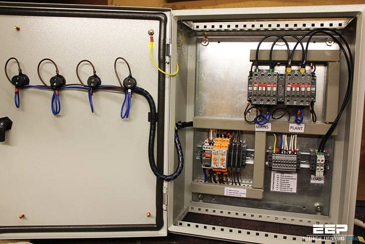
The generator circuit breaker is driven by the digital output 2. A distribution board also known as panelboard breaker panel or electric panel is a component of an electricity supply system that divides an electrical power feed into subsidiary circuits while providing a protective fuse or circuit breaker for each circuit in a common enclosure.
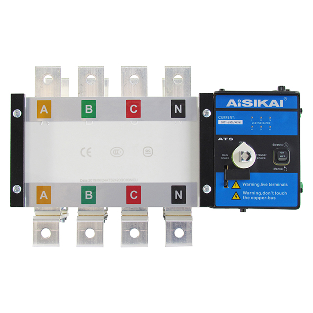
Download Aisikai Electric
Ats circuit diagram download. Instructor runner cyberlink limited. The generator 1 voltage is connected to l1 l3 via protection fuses 4. The following article explains an enhanced automatic transfer switch ats circuit which includes several customized sequential changeover relay stages making the system truly smart. The dashboard is supplied by the terminal blade 1554 via a 5 amp fuse. Generac ats wiring diagram download. This interlock is not optional.
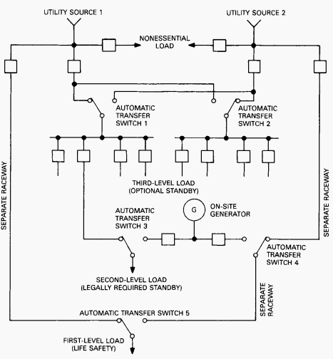
Figure 1 shows automatic transfer between two low voltage utility suppliesutility source 1 is the normal power line and utility source 2 is a separate utility supply providing emergency power. It shows the elements of the circuit as. This is auto change over switch use with ats circuit. Both circuit breakers are normally closed. Auto transfer switch wiring diagram wiring diagram radixtheme. The interlock rides on top of the single throw motorized breaker mechanisms.
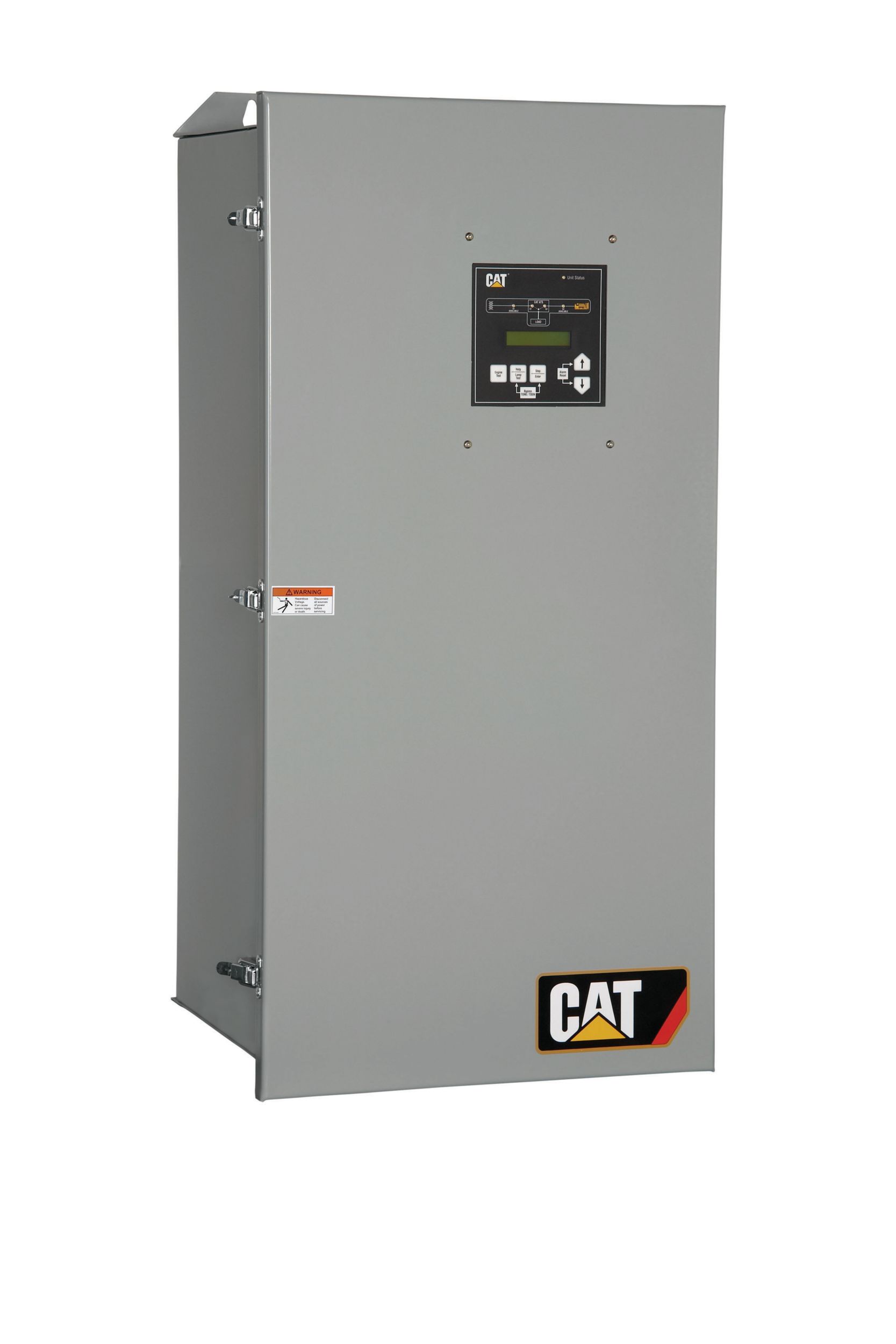
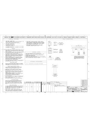
Eatons molded case type automatic transfer switch with self protecting main contacts is designed to provide unmatched withstand close on performance for standby power applications requiring open transition. A wiring diagram is a simplified conventional photographic depiction of an electric circuit. Breaker contactor or motorised switch socomec diagram. 12 selection the size of automatic transfer switch 13 automatic transfer switch components 14 modes of operation 15 schematic circuit diagram for automatic transfer switch 16 recommended cable size 17 specifications 171 general specification 172 controller specification 18 ordering information 19 detailed drawings. Designed and written by. Technical information 3 standard diagrams transfer between 2 sources 1 bus bar.
The load must be able to tolerate the few cycles of interruption while the automatic transfer device operates. Motorised switch cl ncl g q1 q2 ats automatic transfer switch protection arent shown on the following schemes summary. Updated ats circuit diagram with complete ic 4060 and ic 555 wiring details. A circuit breaker ats is made of two single throw devices this makes it necessary to add an interlock. If you need any professional trainingplease contract our training in charge md. The be24 generator auto start circuit diagram is a simple and intuitive diagram.
Transfer switches can be configured with integral overcurrent protection and a service entrance rating. The power contactor ats is a true double throw device interlocking is inherent. Ats wiring diagram for standby generator collections of generac ats wiring diagram download. The interlock is built into the drive mech anism.
