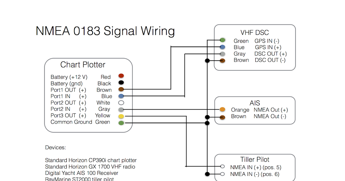
Mount the vhf antenna section 45 6. 0183 network wiring is extended the talker color code should be used for cabling between barrier strips.

How Can I Connect Ais To My Laptop Cruisers Amp Sailing Forums
Ais pilot plug wiring diagram. See your ais installation guide to connect power to the ais equipment and finish the installation. This means you can only run one program at a. Variety of raymarine seatalk wiring diagram. Ar200 video stabilization module. Connect the ais data cables de 9 connector to the null modem. The flushmount panel can be removed if it is not required.
Windows only allows one process to access a com port device including virtual com port usb devices at a time. If the pilot plug on the r4 display is not to be used mount the external pilot plug section 44 5. Ais650 ais700 ais950 ais4000. Icom m506 to pilot plug wiring diagram is there a simple plug and play gps antenna that will function properly. This diagram shall identify all interface modules and junction barrier strips included in the installation and shall include the name and location of each device or module. Wiring 233 how to connect the fa 1703 pilot plug unit optional the fa 1703 is shipped with a flushmount panel attached.
A wiring diagram is a streamlined traditional pictorial representation of an electric circuit. As pc2 de 9 connector null modem ais de 9 connector connecting an ais to the helix series with a de 9 connection ais helix series. Constant running pumps evolution autopilot. The garmin 400 and 500 series plotters are some of the most popular small boat chart plotters on the market and it is not surprising that we get many enquiries about how to connect our products to them. Hydraulic linear drives hydraulic pumps. Proceed to section 3 to set the baud rate.
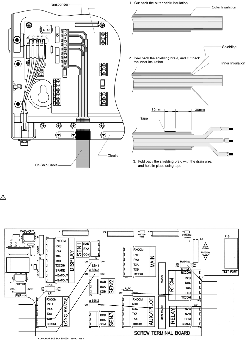
Retired legacy ais. Power up the system section 63 9. All diagrams shall be. Set configuration parameters. Pilot plug assembly 89 081 wiring instructions the pilot plug assembly is supplied already wired to a 20 m cable. Normally customers just want to add an ais receiver or transponder to.
Mount the gps antenna section 46 7. When this is complete plug in the usb ais device to see whether it is now installed correctly. The instructions given here are specific to the mcmurdo m 1 but by following the principle and the named connections it should be possible to install this accessory. The example figures below show the fa 1703 without a flushmount panel. How to terminate com ports for iec 61162 12 signal 2. The free end of this cable is to be connected to the ais system.
Streetpilot iii gps iiiiiv comparable to garmin ga 26c remote antenna it is an icom m ais and after checking the specs right now it can. In some cases a reboot may be necessary if there are driver conflicts or other issues. Connect the wiring to the r4 transponder and r4 display section 5 and appendix a9 8. It shows the parts of the circuit as simplified forms as well as the power and signal links in between the tools.


