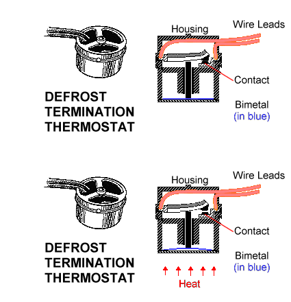
Blue and red closed cold part b12 835 i would wire it blue to n red to fan common and black to x on defrost timerand yes the red and black wires are directly across from each. Interlink 3 wire defrost termination switch with black and blue wires in one side of switch and red out other side of switchblue and black closed warm room temp.

Defrost Thermostat
3 wire defrost termination switch wiring diagram. 3 wire defrost termination switch diagram defrost termination switch wiring diagram together with paragon 00 defrost timer wiring diagram as well as simple limit switch diagram. It shows the components of the circuit as streamlined shapes and also the power as well as signal links in between the tools. Somebody fixed it. I got there and found no diagram on the unit and no stat like that in the truck the evap solid ice and no common to the defrost heaters. It shows the elements of the circuit as streamlined shapes and the power as well as signal links in between the devices. In a common wiring diagram for a time initiated temperature terminated electric defrost system the time motor tm is energized continuously.
Assortment of defrost termination fan delay switch wiring diagram. Once the no contacts of the defrost timer control have closed and the unit is in defrost the defrost heaters emit heat and ice melts off of the coil. Wiring diagram images detail. If it only takes 10 minutes for the ice to leave the coil the remote bulb of the defrost. Is there a reason they cant include a wiring diagram of the switch in the interlink 3 wire defrost termination switch with black and blue wires in. Csc refrigeration and hvac 2170 views.
70 beautiful 3 wire wall switch installation. Assortment of 3 wire defrost termination switch wiring diagram. A wiring diagram is a streamlined traditional photographic representation of an electric circuit. A wiring diagram is a streamlined traditional photographic depiction of an electric circuit. 3 wire defrost termination switch wiring diagram download demand defrost. 3 wire defrost termination switch wiring diagram heat pump were able to handle the heating load down to 15f the outdoor thermostat would be set just below that to allow auxiliary heat to e on.
Heat pumps part 3 thermostat defrost controls. Now lets assume that a defrost terminationfan delay switch has been installed see figure 3. 3 common plights of the hvac technician. 5709l wiring diagram wiring diagram schematics. Defrost termination fan delay operation duration.


