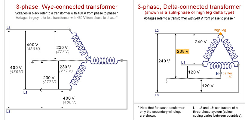
3 shows this same isolated transformer connected as a stepdown autotransformer while fig. Square d buck boost transformer wiring diagram sample.
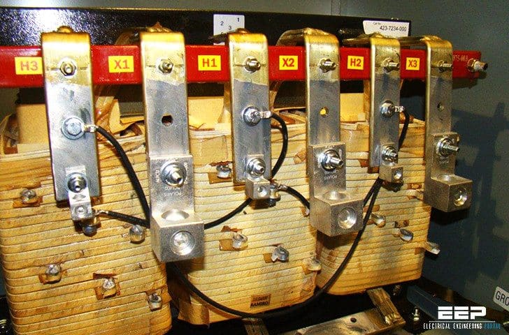
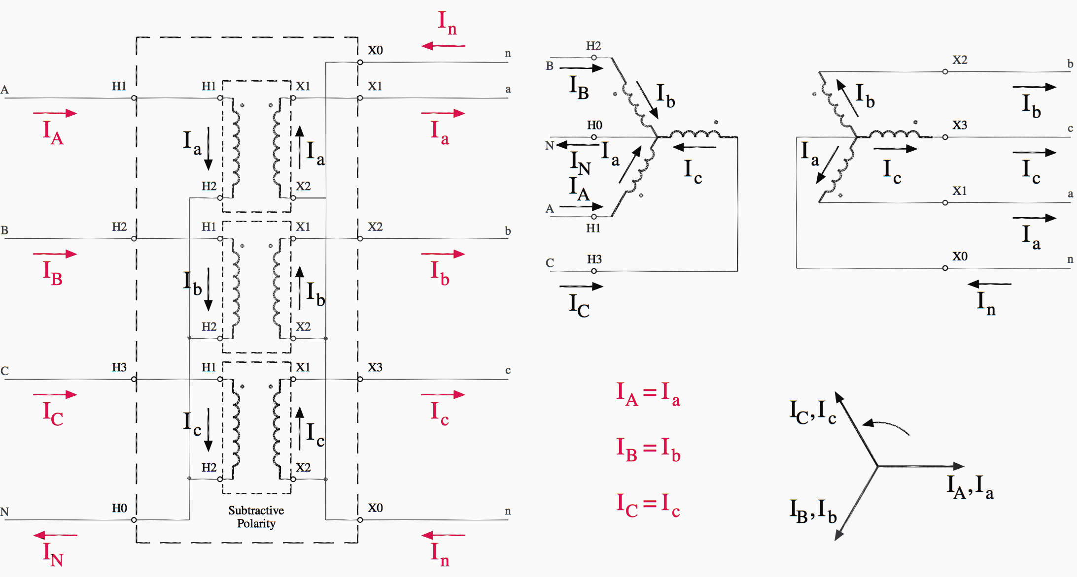
Easy Understanding Of 3 Phase Transformer Connections Delta
3 phase transformer wiring diagram. Buck and boost transformer wiring diagram collections of 3 phase buck boost transformer wiring diagram popular acme. The first symbol indicates the connection of the primary and the second symbol is the. Single phase transformer primary and secondary wiring product line. Three individual transformers are to be connected together to transform power from one three phase system to another. Transformers are delivered in an unconnected condition and must be configured for the system need. A wiring diagram is a streamlined standard pictorial representation of an electric circuit.
Step up transformer 208 to 480 wiring diagram. A three phase transformer is built for a specific connection and voltage transformation and the unit will have a nameplate with the internal connections shown. Collection of 3 phase transformer wiring diagram. Single phase transformer primary and secondary wiring. One disadvantage of delta connected three phase transformers is that each transformer must be wound for the full line voltage in our example above 100v and for. In a delta connected dd group of transformers the line voltage v l is equal to the supply voltage v l v sbut the current in each phase winding is given as.
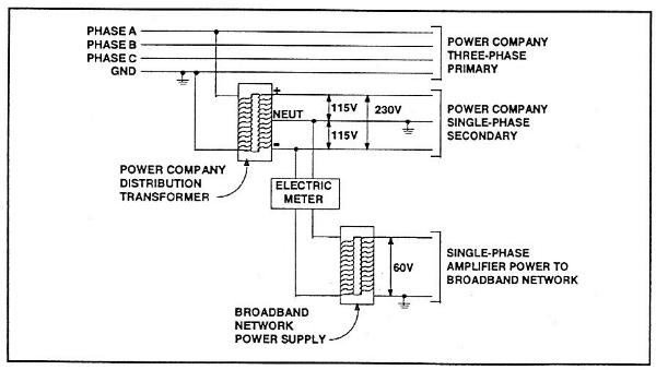
Phase wiring for y y transformer. A 10 kva transformer volt secondary is to service an 8 kva. According to the data sheet the input for my configuration should be. The four basic connections are. Applies to energy efficient ee type transformers by squaredschneider electric cause. 2 is a wiring diagram of an isolated transformer including the input and output voltage at each winding.
1 3 i l of the line current where i l is the line current. A buck booster wiring wire center. 3 phase step up transformer 240 to 480 wiring diagram wiring diagram is a simplified pleasing pictorial representation of an electrical circuitit shows the components of the circuit as simplified shapes and the capability and signal contacts in the company of the devices. Please study the transformer connections shown in figs. When a single unit or bank of three is used there are four types of connections. It shows the parts of the circuit as streamlined forms and also the power as well as signal links between the tools.
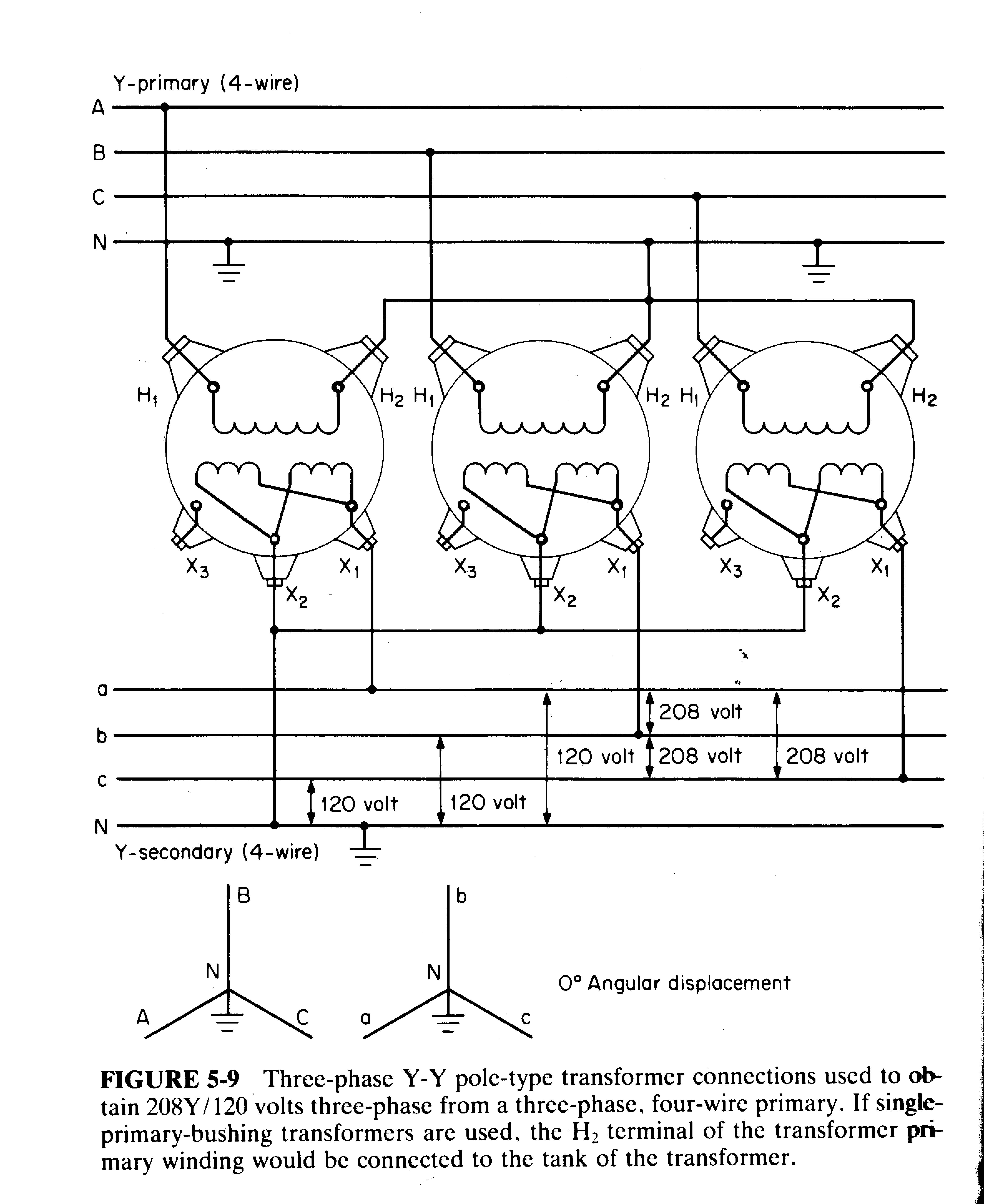
Phase wiring for y y. Y y y y and. 2 3 and 4. A volt primary transformer with a volt secondary is operated at volts regardless of whether the source is three phase 3 wire or three phase 4 wire. Jefferson electric transformer while three phase devices are usually the more cost effective option the single phase option provides more versatility and can be attractive from a reliability and maintenance standpoint. Easy understanding of 3 phase transformer connections deltadelta wyewye deltawye and wyedelta on photo.
First ill show the wiring connections for a y y configuration. Inputs a 1 a 2 a 3 may be wired either δ or y as may outputs b 1 b 2 b 3.


