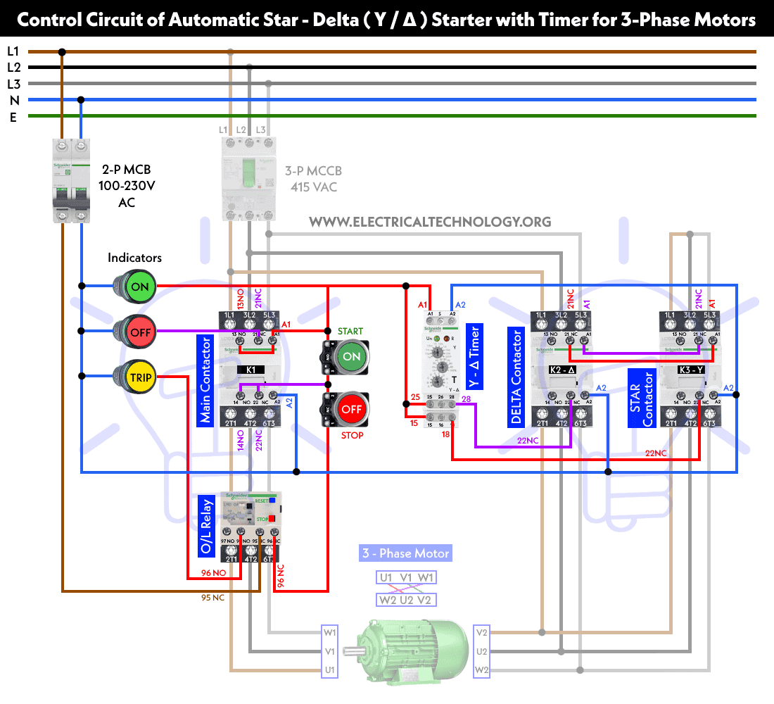
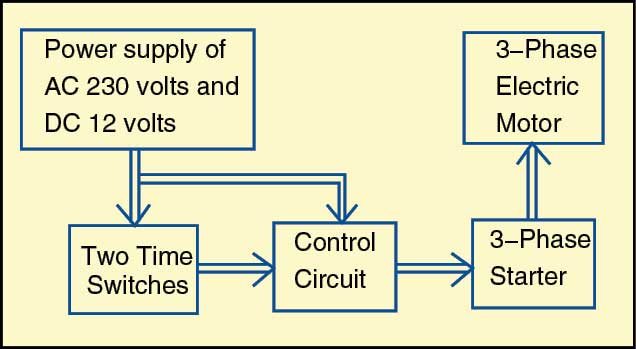
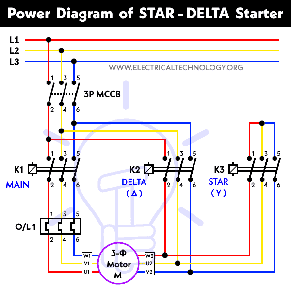
It uses two contactors two auxiliary contact blocks an overload relay a mechanical interlock two normally open start pushbuttons a normally closed stop pushbutton and a power supply with a fuse. Star delta y δ 3 phase motor starting method by automatic star delta starter with timer.

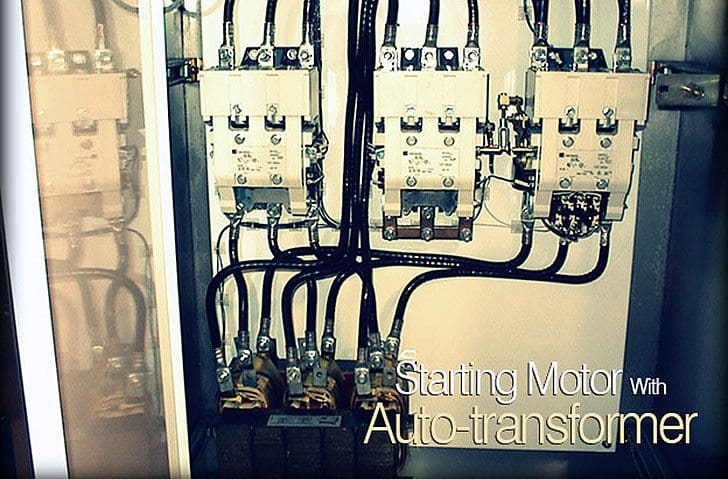
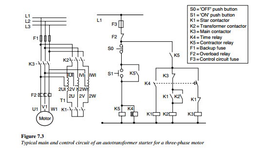
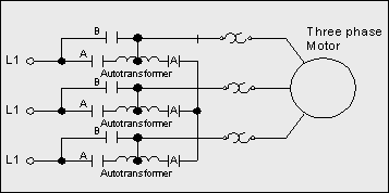
Zm 2613 Autotransformer Wiring Diagram Schematic Wiring
3 phase motor auto starter wiring diagram. We have a saylor beall air compressor we are trying to get wired up. Three phase motor connection stardelta without timer power control diagrams. If you have a 120v coil instead of running a line from coil overload l2 you must run coil overload neutral. Line diagrams also called schematic or elementary dia grams show the circuits which form the basic operation of the controller. Assortment of 3 phase motor starter wiring diagram pdf. This diagram is for 3 phase reversing motor control with 24 vdc control voltage.
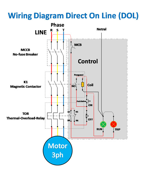
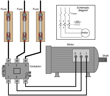
Is a typical wiring diagram for a three phase mag netic starter. How to wire a single phase compressor motor starter. From l1 the phase current flows to thermal overload contact through fuse then off push button on push button interlocking contact 2 and. Typical wiring diagram line diagrams show circuits of the operation of the controller. The starter relay is another switch that is used to control the starting circuit. 1car starter wiring diagram non relay control type.
Operation working of automatic star delta starter. Time lapse of schematic diagram drawn into a wire diagram and the wiring of the magnetic motor starter. Wiring diagram book a1 15 b1 b2 16 18 b3 a2 b1 b3 15 supply voltage 16 18 l m h 2 levels b2 l1 f u 1 460 v f u 2. In the start control circuit the relay is connected in series with the battery to shorten the transmission of the large current cable length. Stardelta starter without timer power control diagrams wiring diagrams. Line voltage control three phase 3ph motor starter controlling a three phase motor rev 08 aug 2006 the above wiring diagram assumes your magnetic starter has a 240v coil.
It shows the parts of the circuit as simplified shapes and also the power and also signal links in between the tools. Overload relays ac motors dc motors wiring capacitors resistors semiconductors table 1 standard elementary diagram symbols contd. Line voltage control three phase 3ph motor starter controlling a three phase motor rev 08 aug 2006 the above wiring diagram assumes your magnetic starter has a 240v coil. They do not indicate the physical relation. 1 phase 2 phase 4 wire 3 phase line markings l1 l2 l1 l3. 3 phase motor starter wiring diagram pdf.
Phase 1 l2 l4. Control 3 phase motor from more than two places power control diagrams. Three phase motor connection schematic power and control wiring installation diagrams. Phase 2 l1 l2 l3. A wiring diagram is a streamlined conventional photographic representation of an electrical circuit.

