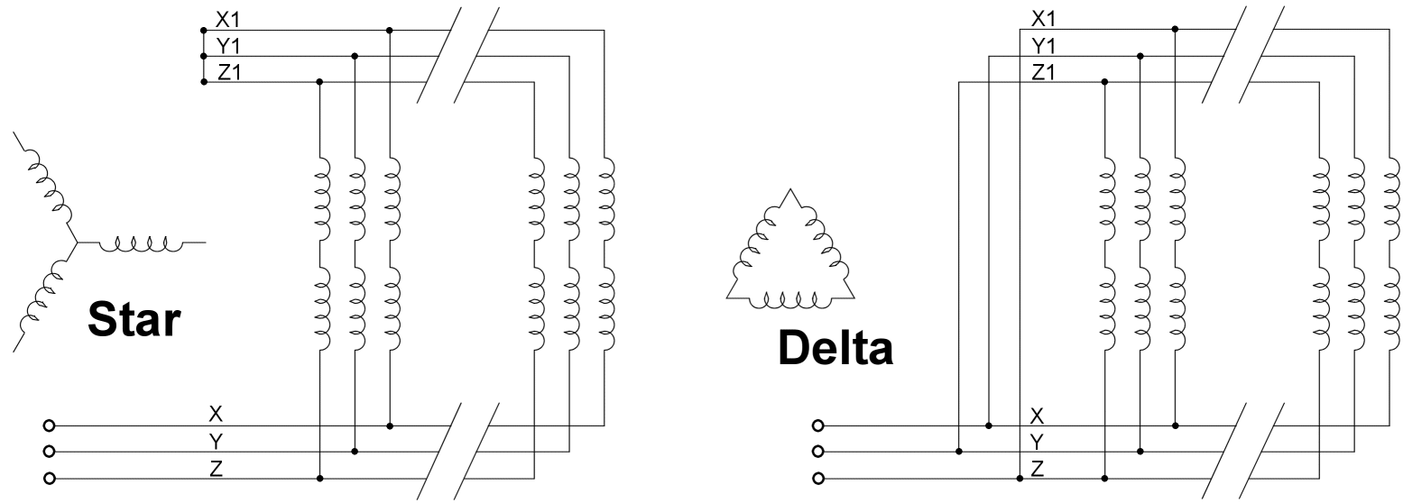
Starting current the generator voltage dips temporarily. Star 3 phase 4 wire insulation.

Wiring Diagram Generator Three Phase
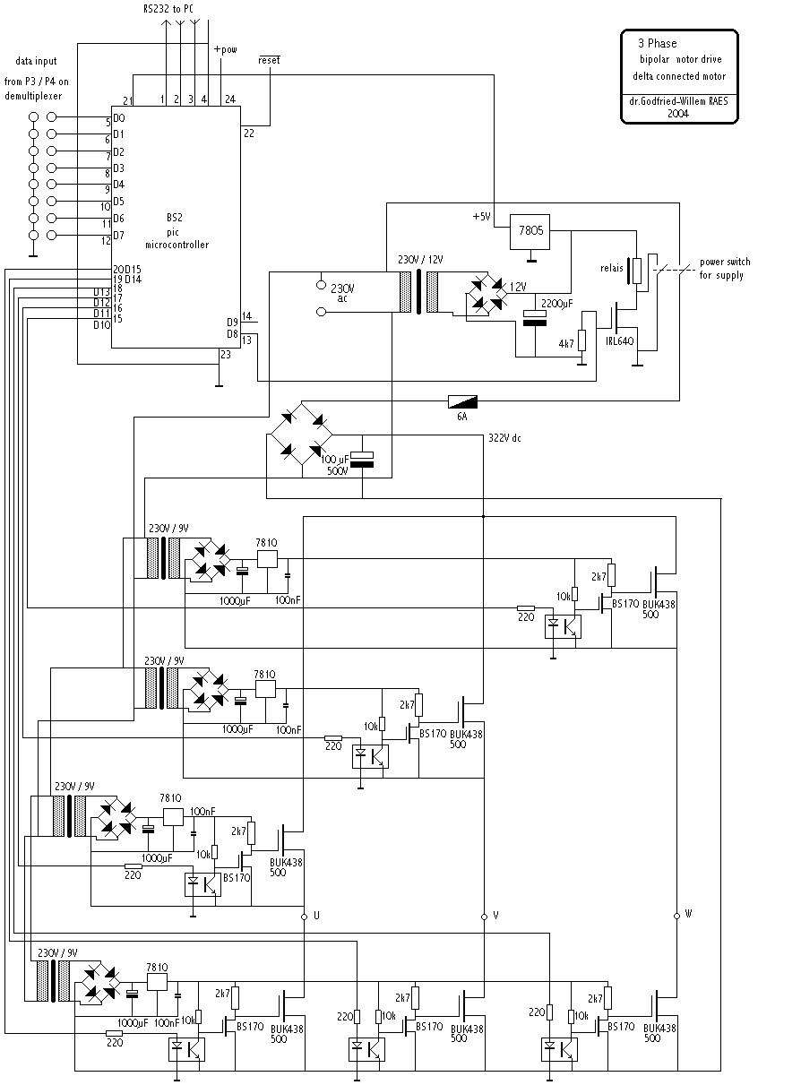
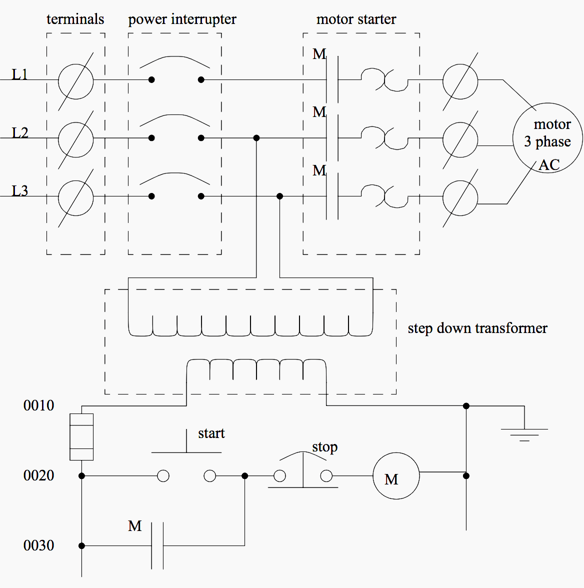
3 phase generator wiring diagram pdf. Busbars carries this three phase power and from which individual connections are brought out to individual loads through cables. Single phase wiring diagrams always use wiring diagram supplied on motor nameplate. It shows the parts of the circuit as simplified shapes and also the power and also signal links in between the tools. W2 cj2 ui vi wi w2 cj2 ui vi wi a cow voltage y high voltage z t4 til t12. Magnaplus generators generally supply 3 to 4 horsepower per generator kw in motor starting capability. Rotor wiring class f 2 characteristic voltage deviation.
A three phase ac generator is designed to produce threephase ac power by building more coils in the stator around the rotor. The three coils are equally spaced 120 apart around the inside of the stator. If the motor is too large for the generator the generators voltage dips greater than 30 percent. This is the same connection as we discussed above for single phase wiring expect that there are three phase wires instead of line and neutral. Output voltage and frequency as shown in the wiring diagram below. Assortment of 3 phase motor starter wiring diagram pdf.
Three phase wiring diagrams always use wiring diagram supplied on motor nameplate colored leads are only applicable on the new rolled steel motor lines. As shown in figure 2 an electromagnet placed in the center of. The 3 phase revolving field generator is constructed by placing the three sets of single phase windings 120 mechanical degrees apart on a metal core around the inside of a metal housing that supports the core the stator assembly. Connect output wiring to the output terminals u1 and u2 inside the terminal box of the generator. A wiring diagram is a streamlined conventional photographic representation of an electrical circuit. The 3 phase revolving field generator.
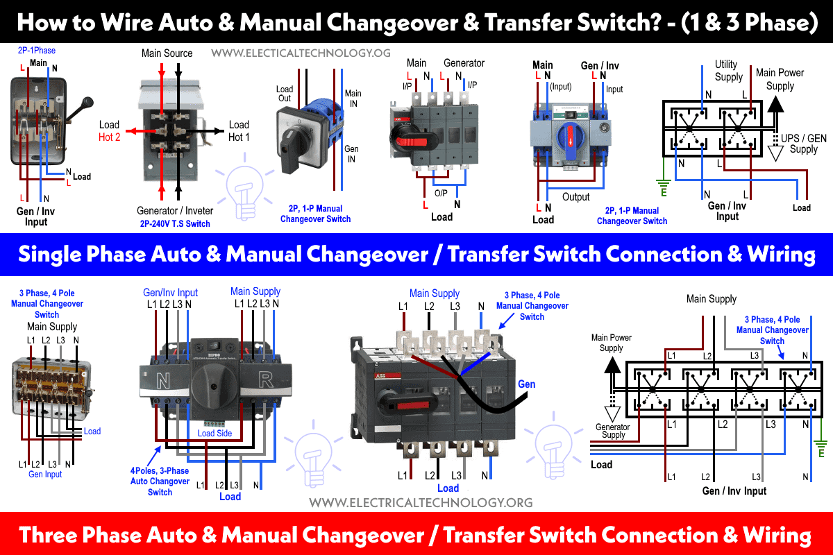
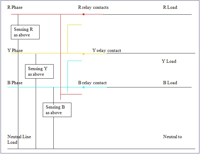
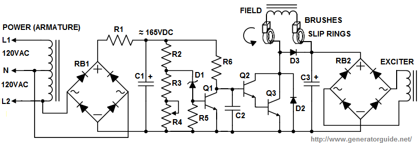
Rotating field self ventilation exciting method. 3 phase manual changeover switch wiring diagram for generator with complete installation guide the 3 phase manual changeover switch wiring diagram is too simple and easy connection. Brushless ac exciter wiring. The figure below shows schematic diagram for industrial three phase wiring. Three phase generator remarks 1 alternator model. The three phase utility power as l 1 l 2 l 3 n are directly connected to the upper side of manual changeover switch while the backup power of three phase generator is connected to the first four.
Three phase power from the utilities is connected to the main breaker through three phase energy meter. The 3 phase revolving armature generator. Stator wiring class f. For better understanding kindly read the below single phase handle type manual transfer switch post. Pay particular attention to making sure that the wires connected to the generator output are of a heavy enough wire gauge to carry the output current rated output current. Less than 10 for the nominal value.
This may result in the motor starter de energizing or the motor stalling. The armature coils are wired so that the generator has three separate output voltages that differ in phase by 1200.
