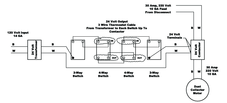
However working on your circuit breaker box and electrical system can lead to serious injury or death if you dont know what youre doing so hire an electrician if you don. Wiring a contactor is a safe method for controlling electrical power.

230v Single Phase Motor Wiring Diagram Ge Wiring Diagram Images
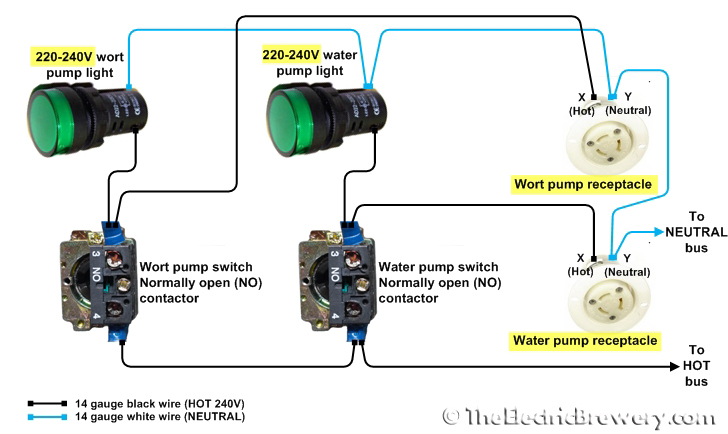
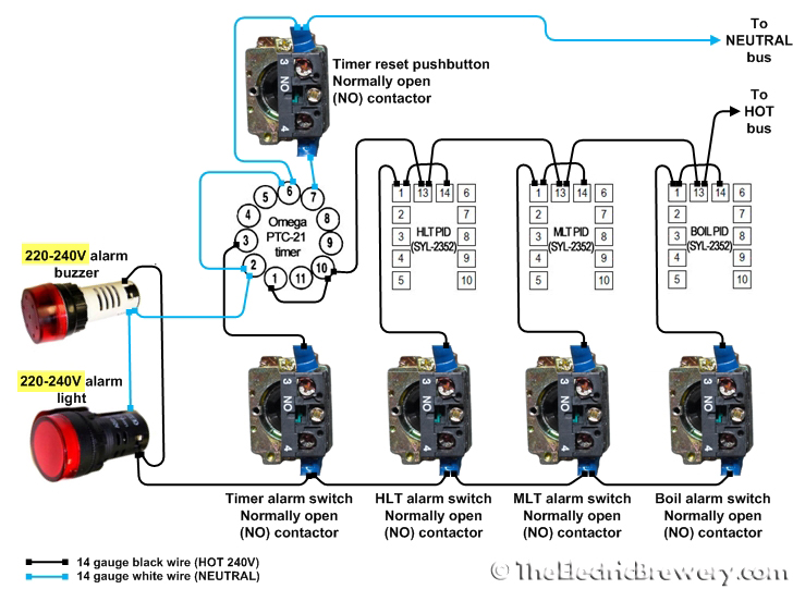
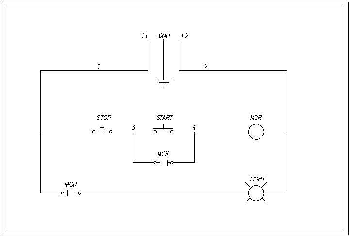
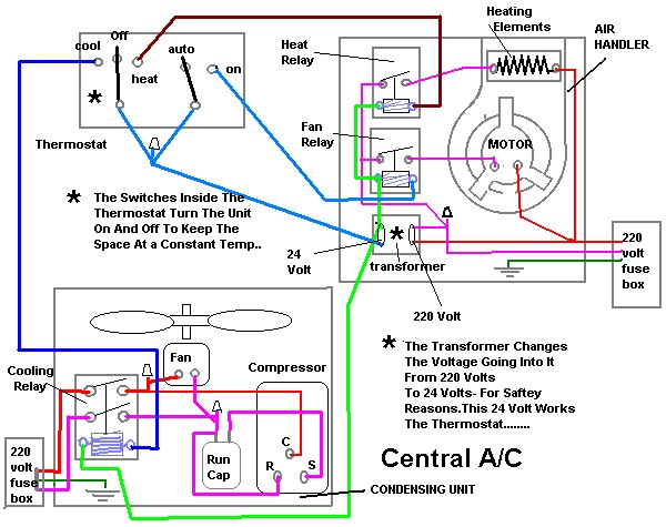
220 volt contactor wiring diagram. Most single phase 220 volt alternating current ac motors are used for residential applications in well water pumping or air conditioning applications. With this sort of an illustrative manual you are going to have the ability to troubleshoot stop and total your tasks without difficulty. Typically a contactor is activated by a remote switch or other controlling electrical device. Each part should be set and connected with different parts in particular way. Each part should be set and connected with other parts in particular way. These lines far exceed the 120 volts ac standard in most homes.
Single phase 220 volt ac motors are really two phase 240 volt motors especially when compared to three phase 208 volt motors and single phase 120 volt motors. If not the arrangement wont function as it ought to be. Wiring a new 220 outlet is a project that someone who has experience working with electricity can do safely by working carefully and following the proper precautions. Friends ye video bahut important video hai because is video me ham practically janne wale hai ki ak contactor ke connection kaise kiye jaate hai to aap is video ko poora jarur dekhiyega taki apke. If not the arrangement will not work as it should be. 240 volts ac and 480 volts ac are commonly used for these large pieces of.
The low voltage wiring would be connected to a 240 volt relay contactor which would have a low voltage coil which matches to control voltage that is used. 240 volt contactor wiring diagram 220 volt contactor wiring diagram 240 volt coil contactor wiring diagram 240 volt contactor wiring diagram every electric structure is made up of various different parts. The main advantage in using a contactor is that the switch can be powered by a different and lower power source from the main contactor power supply. Typical low volt control circuits are 24 volts ac therefore low volt control wiring may be used however the gauge of the control circuit wire must be sized according to the length of the. 240 volt contactor wiring diagram 220 volt contactor wiring diagram 240 volt coil contactor wiring diagram 240 volt contactor wiring diagram every electrical arrangement consists of various distinct pieces. How to wire a contactor.
240 volt contactor wiring diagram you will need a comprehensive professional and easy to know wiring diagram. Many large pieces of equipment are powered directly from high voltage lines.


