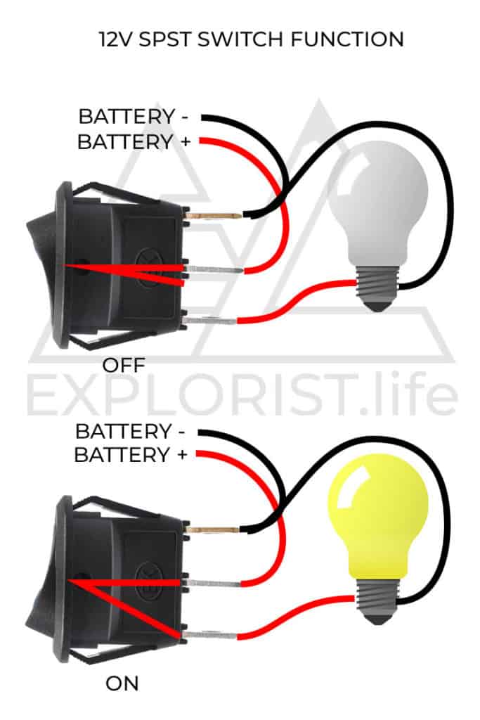
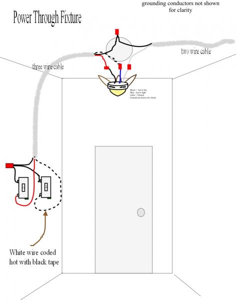
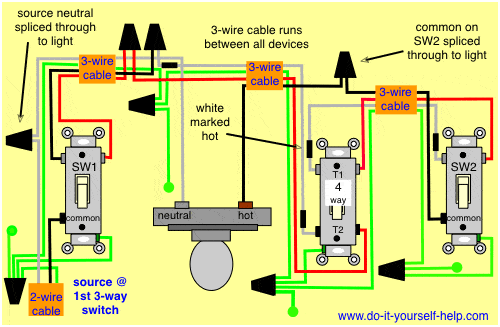
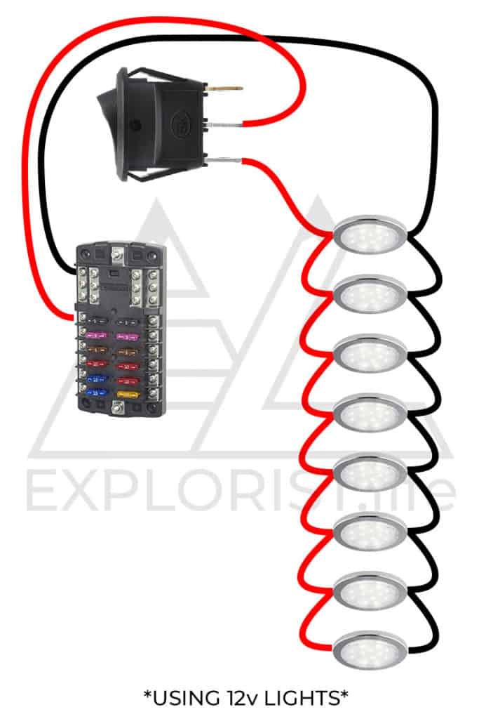
The method 1 is relatively easy. At the lights the hot source is spliced to the black wire running between lights it does not connect to the lights.
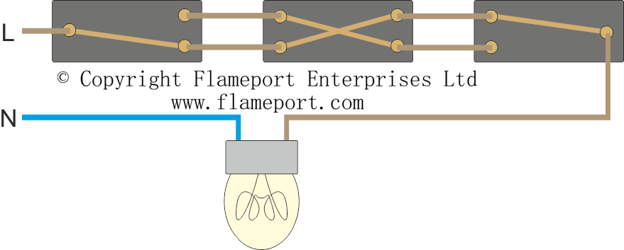
Lighting Circuit Diagrams For 1 2 And 3 Way Switching
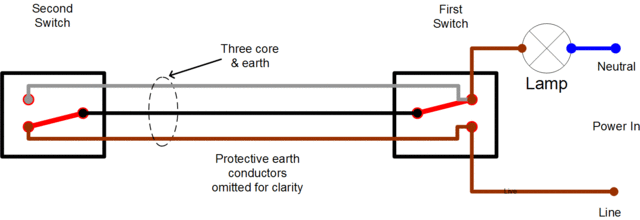
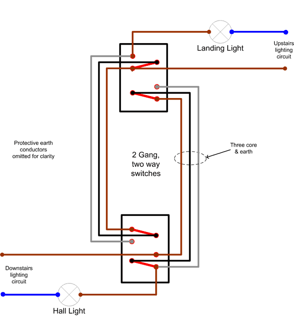
2 way switch 4 wire system. This wiring system may still be encountered in older grandfathered electrical installations. Add a spur socket to ring main. Two terminalpoles are labeled in and two are labeled out pairs of wires called travelers will connect to each side. Notice the black wire is the only wire that we are controlling through the 2 way switch. Two way switching explained how to wire 2 way light switch duration. Here 3 wire cable runs between l1 and l2 2 wire cable runs from the last light to sw1 and more 3 wire cable runs from sw1 to the 4 way switch and then to sw2.
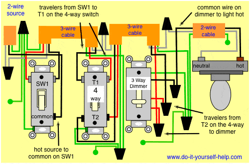
A 4 way switch has 4 terminals or poles. Wiring a three way dimmer switch uses four wires and allows you the convenience of dimming the light from separate switches at opposite ends of a room. Screwdriver tool set with 2 phillips and 14 inch cabinet slim tips 2 pliers and wire. How to wire a 4 way switch system sparky channel. You have an incoming hot wire black going to one screw it does not matter if you use the brass or silver screw on the side of the 2 way switch and a black wire from the other screw on the 2 way switch going to the load light ceiling fan etc. There are really only two basic four way switch wiring methods.
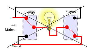
The tester should not register any wattage. With a pair of 3 way switches either can make or break the connection that completes the circuit to the light. Wiring a 3 way light switch is certainly more complicated than that of the more common single pole switch but you can figure it out if you follow our 3 way switch wiring diagram. In order to design a smart switch to retrofit the existing 2 wire installation its either method 1. The engineering mindset 3364493 views. Wiring a 3 way light switch.
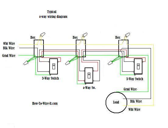
Plus 4 way switch commercial spec. Study the 4 way switch and the manufacturers directions. How to wire a spur socket to ring circuit. At the last fixture it is spliced to the black wire running to the. When the switch is operated current will either travel straight through or crisscross. In order for 4 way switches to work they must be installed between two 3 way switches by 143 wire.
Touch one prong of a two prong electrical tester to the black wire inside the switch box and the other prong to any metal on the box. Lets start wiring a four way switch. Putting a rechargeable battery inside the switch to supply the power to the mcu or method 2. The carter system was a method of wiring 3 way switches in the era of early knob and tube wiringthis now obsolete wiring method has been prohibited by the usa national electrical code since 1923 even in new knob and tube installations which are still permitted under certain circumstances. A four way switch allows the traveller wire from one switch to travel through or criss cross between another switch. Thinking out of the box to make mcu work with the 2 wire wiring system.
