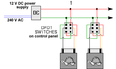
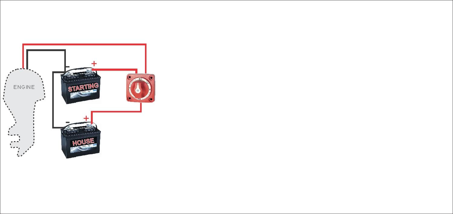
If a multimeter was put across the two colored hot wires however the reading would be 220 volts giving this type of wiring an extra option. Otherwise the arrangement will not work as it should be.
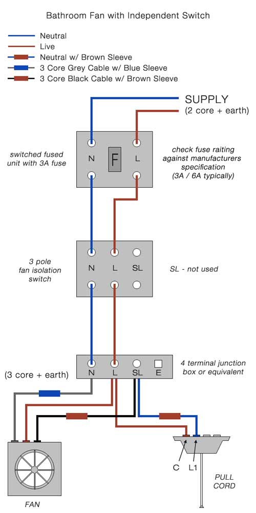
Bathroom Fan Isolator Switch Wiring Diagram H1 Wiring Diagram
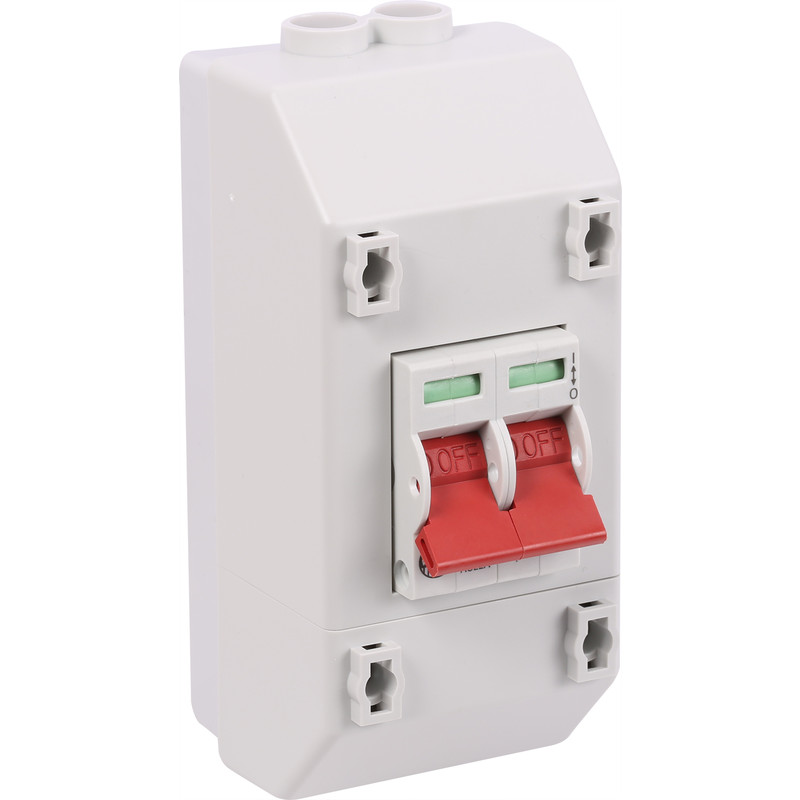
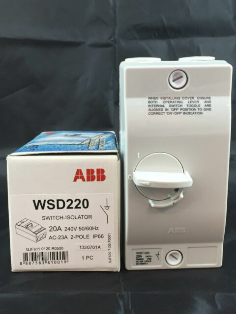
2 pole isolator switch wiring diagram. Rv battery disconnect switch wiring diagram best battery isolator. Two for incoming hots and two for outgoing hots. I explain the wiring using basic wiring. This type of isolator is used to connect an electrical component with 230v and rated with a single phase. With both conductors carrying 120 volts there is an increased risk of injury or property damage. It has four terminals.
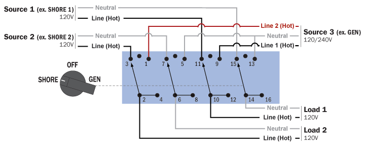
An isolator which includes 4 poles is termed as a 4 pole isolator. A double pole switch is what you need to control a 240 volt device because 240 volt circuits have two hot wires. Dual battery isolator wiring diagram dual battery isolator circuit diagram dual battery isolator switch wiring diagram dual battery isolator wiring diagram every electric structure is made up of various unique pieces. The most obvious and most common is simply to use it to turn off your battery when in storage so that your battery does not drain as quickly and is ready to go when you are. In this kind of electrical isolator three poles use the isolator and remaining one pole will be neutral. Wiring a 20 amp 240 volt switch can be a confusing experience for the average homeowner used to working with standard 110 volt circuits.
Either way the double pole switch is the one to be used since in each instance it cuts both of the colored hot line off and stops the current flow. For one thing both supply wires for this switch carry voltage. Battery isolator wiring schematic collections of battery isolator wiring schematic gallery. An manufacturer of marine hardware and accessories. To light earth. Each component should be placed and linked to other parts in particular way.
A two way switch can be used for one way connection use com and l1 terminals. Two way switching two way switching is used where a light is controlled by two switches. Wiring diagram isolator switch new wiring diagram alternator to. Sure power battery isolator wiring diagram fresh thesamba type 2. For multiple gang switches 2 3 4 6 repeat wiring method for each switch. The difference between a single and double pole switch is that the latter controls two circuits at the same time.
Bathroom exhaust fan wiring diagram for switch to light fokus wiring a bathroom extractor fan with an isolator switch selv bathroom fan wiring diagram base website 1a77d04 bathroom extractor fan wiring diagram uk library how to wire an electric shower uk you. There are many ways to use a perko battery on off switch. Mk fan isolator switch 3 pole 10a. In this video i show how to wire a 3 pole fan isolator switch for a timer fan using 3 core earth cable and for a non timer fan using twin earth cable. For multiple gang switches 2 3 4 6 repeat wiring method for each switch. This switch doesnt use a neutral conductor.


