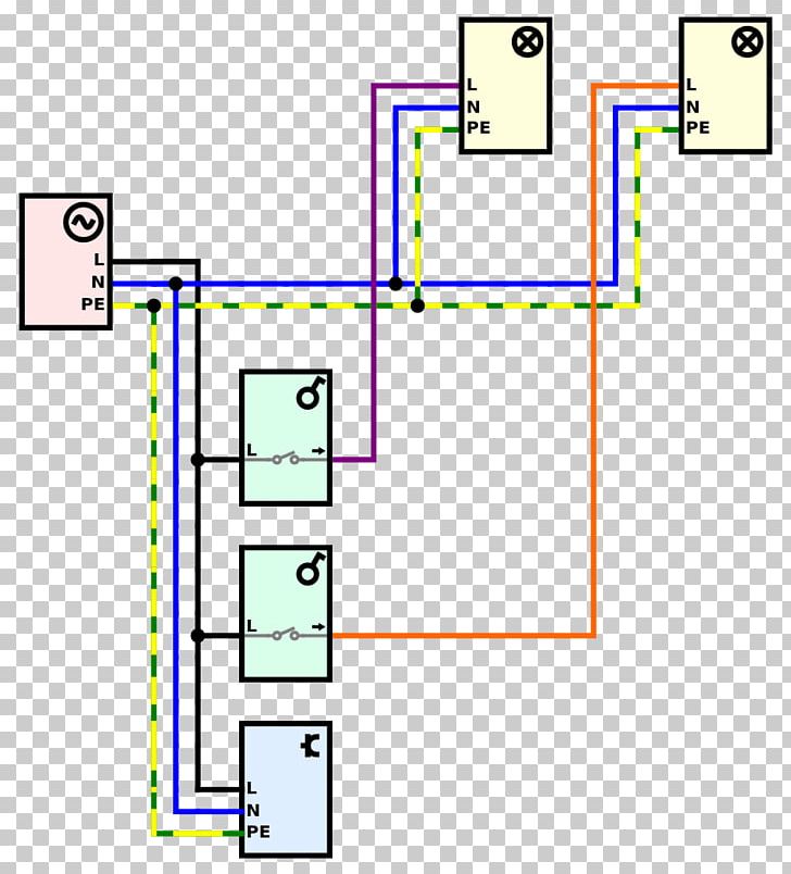
A wiring diagram is a simplified traditional photographic depiction of an electrical circuit. A wiring diagram is a simplified traditional pictorial representation of an electrical circuit.
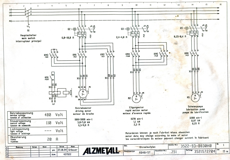
Electrical Contactor Circuit Diagram H1 Wiring Diagram
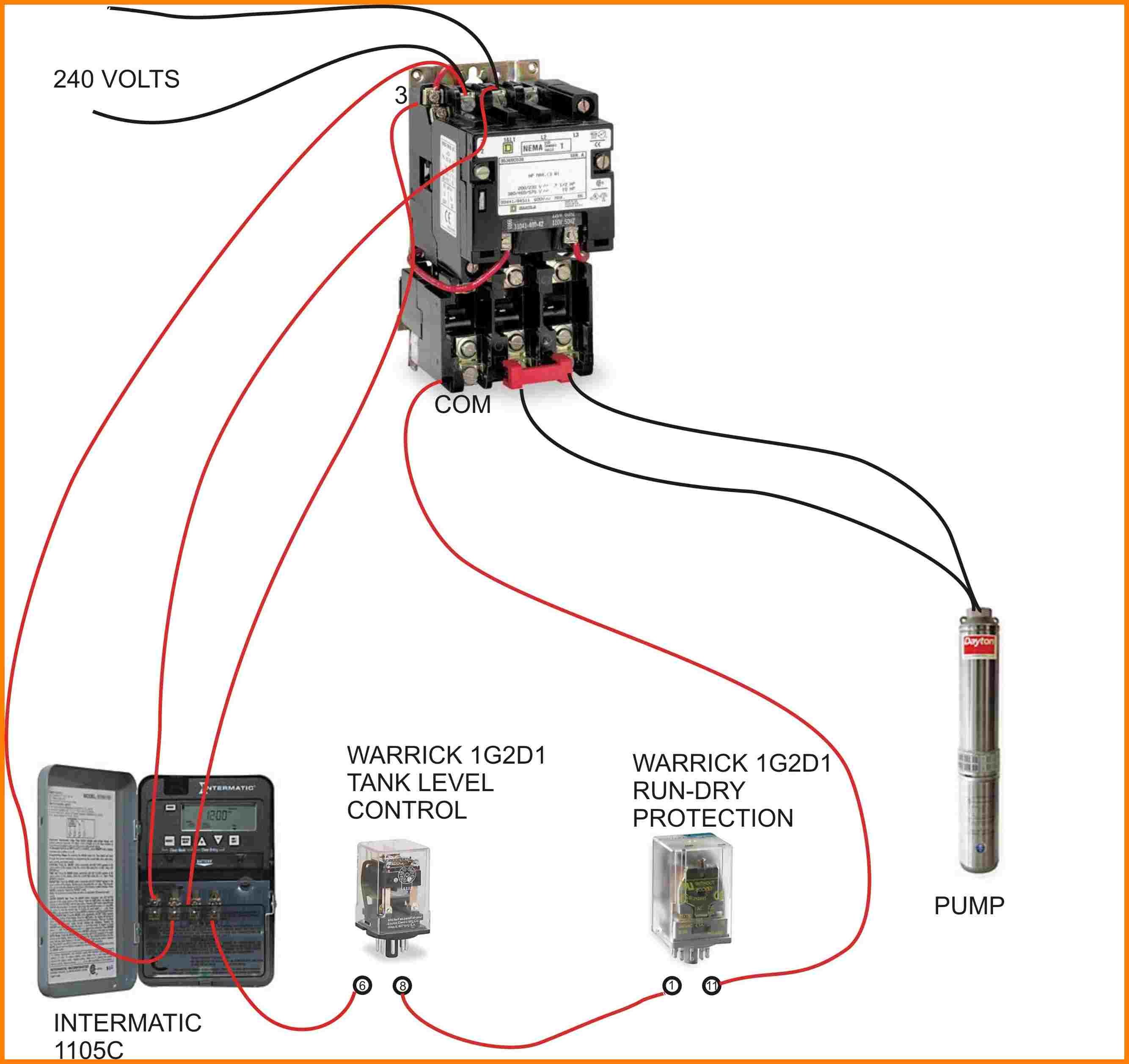
Wiring diagram of electrical contactor. Its is important to. 2 days ago i wired 380 to 440 volts contactor for a 3 phase motor and save these images of contactor in pc. Collection of ac contactor wiring diagram. In the above one phase motor wiring i first connect a 2 pole circuit breaker and after that i connect the supply to motor starter and then i do cont actor coil wiring with normally close push button switch and normally open push button switch and in last i do connection between capacitor. 3 phase motor contactor wiring diagram full size of wiring diagram three phase electrical wiring diagram luxury no nc contactor wiring. It reveals the components of the circuit as streamlined forms and the power and signal links in between the tools.
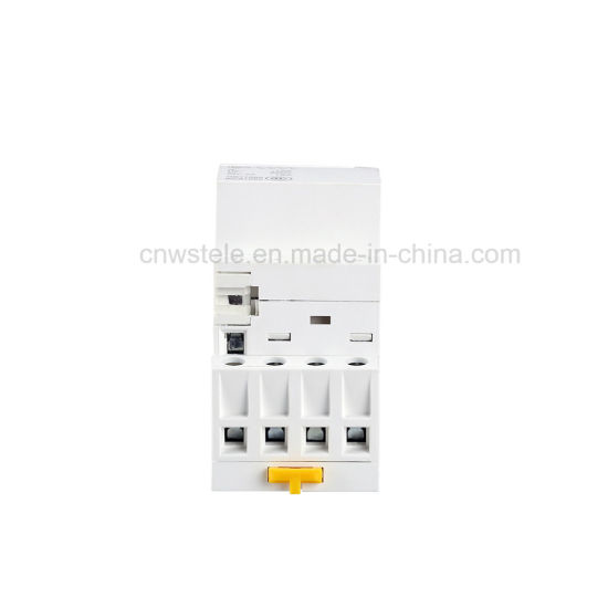
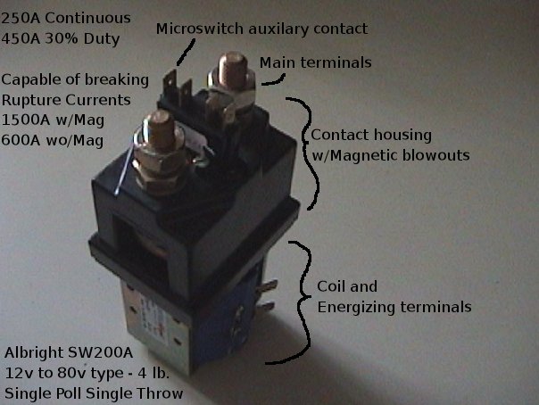
Contactor wiring diagram you will want a comprehensive professional and easy to know wiring diagram. Contactor wiring and i hope after this post you will be able to wire a 3 phase motor i also published a post about 3 phase motor wiring with magnetic contactor and thermal overload relay but today post and contactor wiring diagram is too simple and easy to learn. What is a contactor. With this kind of an illustrative guidebook you will be capable of troubleshoot prevent and complete your projects without difficulty. Note that one one of the contactor acts as a switch for the start button. Variety of 2 pole contactor wiring diagram.
The above diagram is a complete method of single phase motor wiring with circuit breaker and contactor. How does a contactor work. A simple circuit diagram either of the two start buttons will close the contactor either of the stop buttons will open the contactor. It reveals the elements of the circuit as streamlined forms and the power and also signal links between the gadgets.

