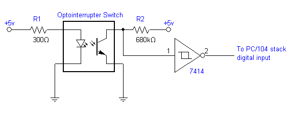
Whilst the above diagram may be used as a pointer and gives a general wiring idea thats typically workable i recommend that before the tryout you must check the wire color codeconnection theme of your optical liquid level sensor. 18 is a waveform chart for illustrating the rising operating speed of the circuit shown in fig.

Optical Mouse
Optical switch circuit diagram. I was looking for exactly this having salvaged a couple of slotted optical sensors from an old printer. Circuit board of the optical mouse the adns 2610 is a small form factor optical mouse sensor based on optical navigation technology which measures changes in position by optically acquiring sequential surface images frames and mathematically determining the direction and magnitude of movement. Simple inverting schmitt trigger. The 555 is proved to be the most versatile and ubiquitous ic all over the worldthis is a possible use. A proximity switch will be in its normal status when it is distant from any detectable object. By definition these switches are non contact sensors using magnetic electric or optical means to sense the proximity of objects.
Just add threshold detection transitor. A proximity switch is one detecting the proximity closeness of some object. How to build simple optical switch november 30 2010 category. 9 thoughts on how to set up a photo interrupter or slotted optical switch on the arduino steven on november 7 2012 at 357 am said. When an object such as a ticket or a small tab that is part of some mechanical system is placed in the sensor slot the beam of infrared light from the led to the phototransistor is blocked turning off the phototransistor. Heres a typical wiring diagram for 5vdc operation of the optical liquid level sensor.
The invention provides a burst type super long distance optical fiber protector based on an soa optical switch which comprises an optical line terminal interface an optical splitter the soa optical switch and a main fiber interface which are connected in sequence wherein the optical splitter is connected with a light detector and a control logic circuit in sequence. This optical switch driver circuit is a preemphasis type. Brilliant thanks for taking the time to write this up. Introduction the 555 is proved to be the most versatile and ubiquitous ic all over the worldthis is a possible use. A simple example of a slotted optical switch is shown in fig 542 with its schematic diagram in fig. And the control logic.
17 is a circuit diagram showing an optical switch driver circuit according to a second embodiment of the present invention. Simple inverting schmitt trigger.


