Power pic rgb with infrared remote controlis a circuit that generates colors using a rgb led and can be controlled using any infrared remote controller capable compatible with the sony sirc code. Ir remote controls switch circuit.
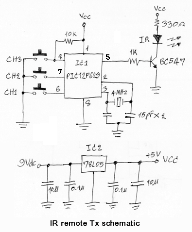
3 Channel Ir Remote Control
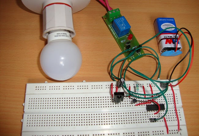
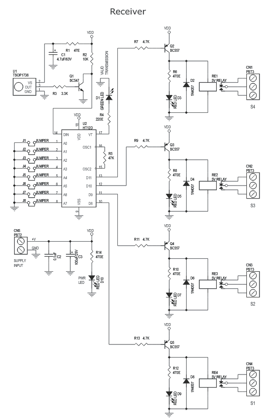
Infrared remote control switch circuit diagram. Both tr3 tr4 will be connected in flip flop form and will still original state. When have the infrared light press button come to the module aperture cause it work to short an output point to ground. Receiver circuit is connected to ac appliance via relay so that we can control the light remotely. In early days remote controls were used to be huge and complex but now. Today we are going to make an interesting project of infrared remote control switch. In this remote controlled switch circuit we are using tv remote to onoff the ac light by pressing any button of remote and using the tsop1738 at receiver end.
Ir transmitter and receiver are used to control any device wirelessly means remotelytv remote and tv are the best example of ir transmitter and receiver. This is the very simple circuit diagram of ir remote control switch. The circuit is using a 5v relay switch at the output from which you can connect any ac appliance like fan light lamp etc. The infrared remote control switch is divided into two sections. We uses normal switch in our daily life and after a long time used to these swithing system we can no more interested in that. In the receiver section there are 3 photodiodes which will detect the infrared signals from the receiver and produce leakage current to the capacitor c1.
Syed saad hasan 1 week ago. In this write up we discuss a couple of these simple infrared remote control circuits designed for controlling any given electrical appliance through an ordinary or tv remote control unit. We have used ic 4017 to convert it into a push on push off switch. Suppose just tr3 works led will glow tr4 will stop on. Tv generally consist tsop1738 as the ir receiver which senses modulated ir pulses and convert them into electrical signal. The ca 3130 op amp is a bicmos operational amplifier and it has a high input impedance a low input current and a high speed performance.
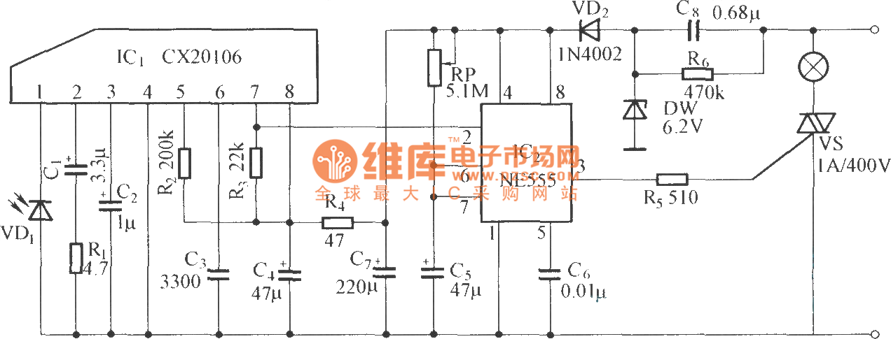
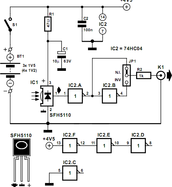
Figure 2 the circuit diagram of infrared switch controlled by a tv remote. Led chaser circuit using transistors electronics projects. Infrared proximity sensor using transistors ir led. This current is given to the inverting input of 3130 ic which will get triggered by this current and give amplified output. Transmitter section and receiver section. This circuit is the third evolution of pic rgb project in which the goal was to control a rgb led and randomly generate colors.
This time the goal is to use a remote control to change the colors. This is a good solution for a unique and so interesting idea to wireless switching system to control the home appliance. The proposed infrared or ir remote control circuit can be used to operate an appliance onoff through any standard tv remote control handset. Circuit diagram of infrared remote control switch. The main components of this ir remote control switch are ca 3130 operational amplifier and 4018 counter. If you want to operate your home electrical appliances remotely then this ir or infrared remote control switch circuit can be ideal for you.
