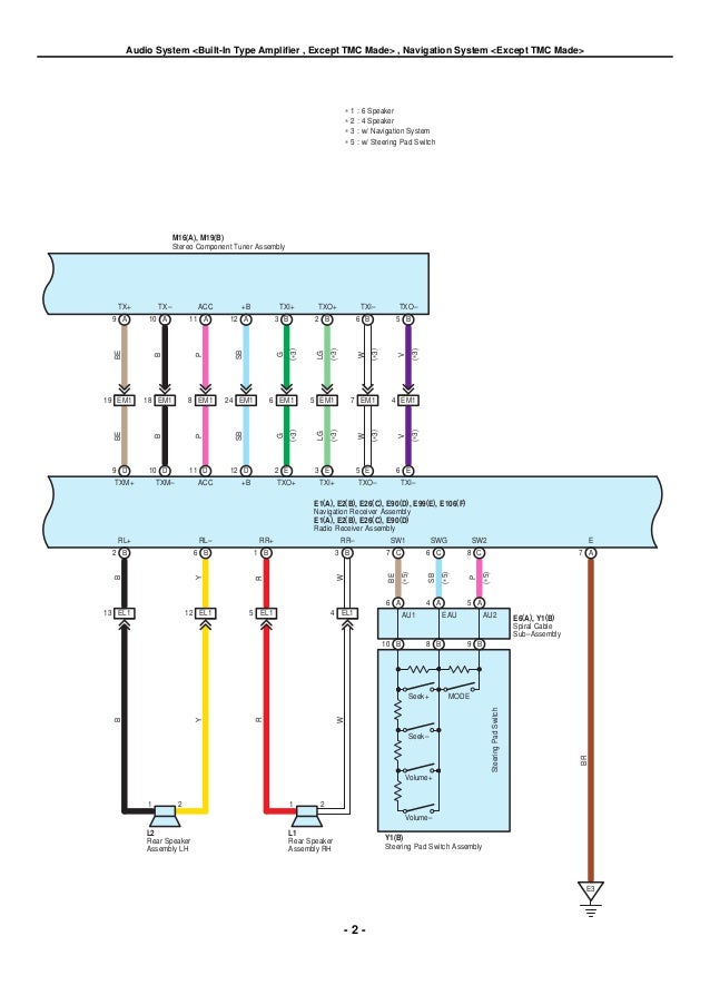
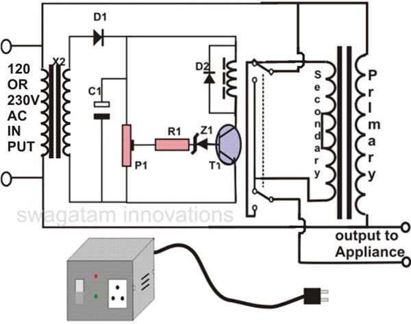
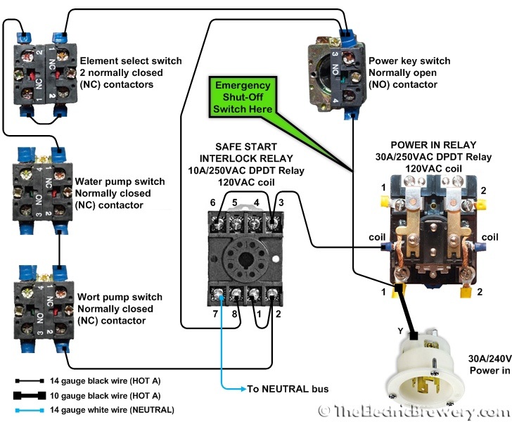
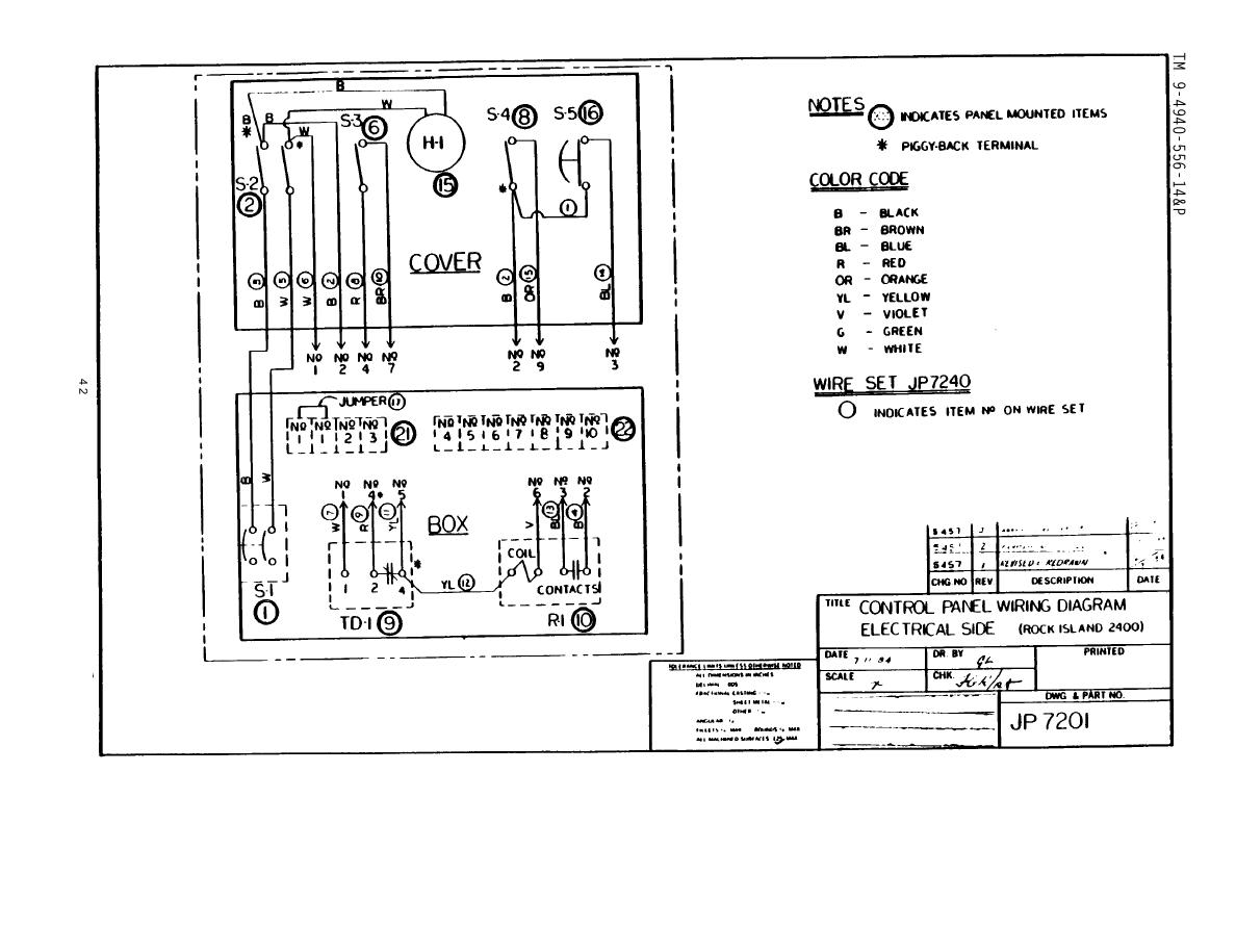
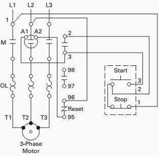
A wiring diagram is a simplified traditional photographic representation of an electric circuit. The first circuit to be discussed is a basic control circuit used throughout industry.

Wiring Diagram For Dummies H1 Wiring Diagram
Electrical control circuit diagram pdf. The line diagram sometimes referred to as an. Many schematic diagrams show only the control circuit. Basics 9 416 kv pump schematic. Basics 13 valve limit switch legend. Basics 11 mov schematic with block included basics 12 12 208 vac panel diagram. Figure 914 shows a start stop push button circuit.
Multi speed 3 phase motor 3 speeds 1 direction power control diagrams. The finished project contains electrical diagrams panel mechanical layout and various lists. One line diagram of simple contactor circuit. You may also read. A wiring diagram is a streamlined traditional photographic representation of an electrical circuit. Basics 6 72 kv 3 line diagram.
A one line diagram or single line diagram is a simplified notation for representing an electrical system. The one line diagram is similar to a block diagram except that electrical elements such as switches circuit breakers transformers and capacitors are shown by standardized schematic symbols. Disconnect circuit interrupter circuit breakers w thermal ol circuit breakers w magnetic ol limit switches foot switches pressure vacuum switches liquid level switches temperature actuated. It reveals the components of the circuit as streamlined forms and the power and also signal connections in between the gadgets. Figure 2circuit drawing line diagram. Basics 8 aov elementary block diagram.
O the project looks like pcsmotordemo1. Assortment of electrical control panel wiring diagram pdf. Basics 7 416 kv 3 line diagram. Basics 10 480 v pump schematic. Schematic diagrams do not always show both control and motor connections. Three phase electrical wiring installation in home iec nec.
How to connect a portable generator to home supply system three methods a simple circuit diagram of contactor with three phase motor. In following the electrical sequence of any circuit however the wiring diagram does not show the connections in a manner that can be easily followed. It shows the elements of the circuit as streamlined shapes and the power and signal links between the gadgets. The diagram symbols in table 1 are used by square d and where applicable conform to nema national electrical manufacturers a ssociation standards. L1 l2 m1 m1 start stop m1 motor to 3. In this way you can always check that you have been through all steps.
This schematic shows both the control circuit and the motor circuit. Tutorial motor control o shows you how to make a small control circuit where all components are found in the component database. A very common form of latch circuit is the simple start stop relay circuit used for motor controls whereby a pair of momentary contact pushbutton switches control the operation of an electric motor. In this particular case i show a low voltage control circuit and a 3 phase higher voltage motor. Basics 14 aov schematic with block included. Assortment of generator wiring diagram and electrical schematics pdf.
For this reason a rearrangement of the circuit elements to form a line diagram is desirable.


