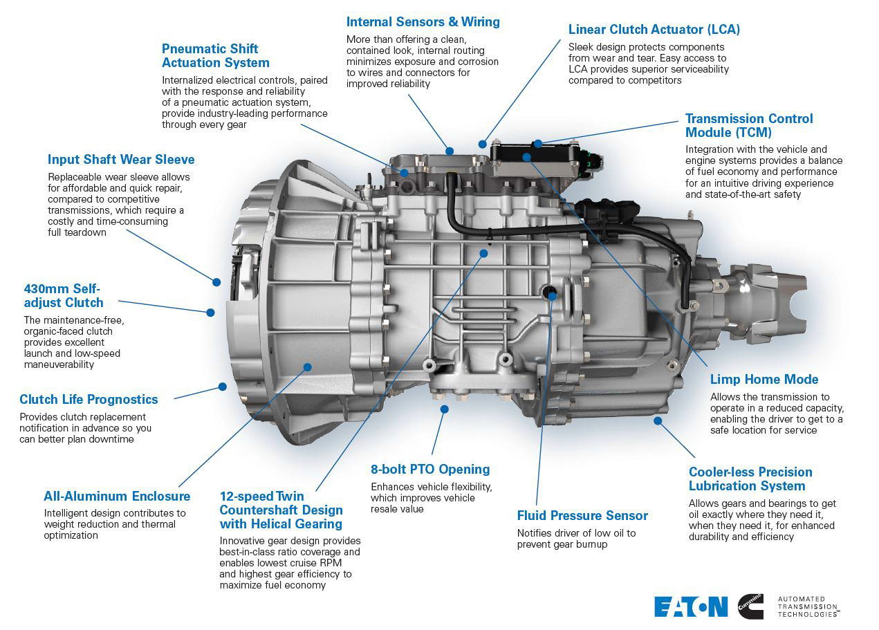
Eaton fuller transmission air line diagram. T3 in accordance with en 61643 1 lightning protection classes iii and iv in accordance with iec 62305 capsuled version.
Eaton Instruction Manual 01
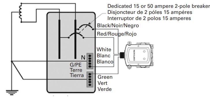
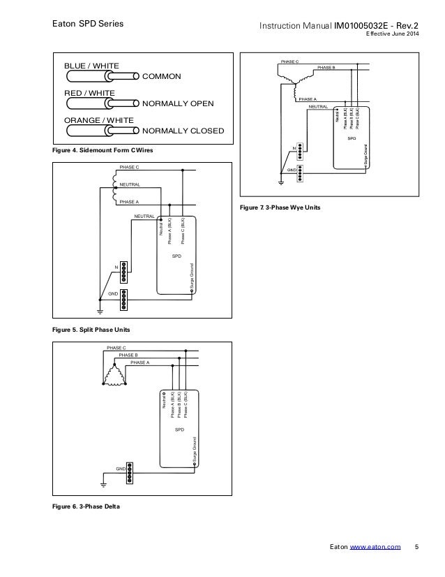
Eaton spd wiring diagram. The ideal mounting location for the eaton spd series is as close as possible to the electrical enclosure. Bus connection figure 4. Locate the electrical systems applicable wiring diagram in section 23. Select the correct wiring diagram for the spd you are install ing. Eatons spd series can be installed next to above or below any existing electrical enclosure. Reference this wiring diagram as necessary in steps 2 3 and 4.
Eatons spd series can be installed next to above or below any existing electrical enclosure. You must refer to this diagram while wiring the spd. Eaton fuller air line diagram imageresizertool eaton fuller air line diagram further eaton 20fuller 20transmission 20parts 20diagram moreover 99 dodge ram 1500 suspension furthermore nv4500 internal diagrams wiring eaton fuller air line diagram best eaton fuller air line diagram furthermore eaton fuller 9 speed transmission diagram in addition 91. Connect the spds neutral wire white to the systems neutral connection not required for. Connect the spds ground wire green to the systems ground connection. English us 1 jul 2014 470 kb.
During the discharge process the device does not issue any hot ionised gasestherefore there is no need for maintaining a safety distance from flammable materials. See figures 6 7 8 and 9 on page 4. Demonstration of eaton switchgear at work solving problems. 23 installation procedures 1. Eaton 93pm universal integrated battery cabinet ibc lw 432v and 480v ibc lhw 432v and 480v installation manual. Controlling and protecting motors.
Reference to applicable standards. Spd type t1 t2 resp. Eaton top wiring kit for type s battery cabinet installation instructions. The classic from eaton. The eaton spd series should be mounted in such a way as to minimize any sharp bends in the wiring conduit. For protecting consumer systems against transient overvoltages caused by indirect lightning strikes and switching operations test class ii according to iec 61643 1a1 spd type t2 according to en 61643 11 spc s hk auxiliary contact for remote signaling can be added can be bussed with all xtra combinations switchgear.
Dimensions for 50 200ka units mounting 880 2235. Select the correct wiring diagram for the spd you are install ing. The ideal mounting location for the eaton spd series is as close as possible to the electrical enclosure. Page 6 eaton spd series instruction manual im01005019e rev. You must refer to this diagram while wiring the spd. 23 installation procedures 1.
Eaton spd series instruction manual im01005032e. The eaton spd series should be mounted in such a way as to minimize any sharp bends in the wiring conduit. The wiring manual online as flip manual the wiring manual in pdf. Extensive collection of switches for eatons industrial switchgear. 5 surge protective device for integrated units effective november 2013 figure 6. Wiring single phase units 230 l figure 8.


