Discrete input signals to the plc from real world switches are read by a ladder diagram program by contacts referenced to those input channels. Contactor wiring diagram wiring diagrams lose contactor wiring diagram additionally wiring diagram provides you with the time body in which the assignments are for being finished.

2 Pole Contactor Wiring Diagram C3 Wiring Diagram
Coil contactor diagram. 2 incomplete catalog number. Dc coil contactor size 56 see selection table for details. 3 bulk pack quantities are available in quantities of 50 contact local sales office. Contactors are used to provide this isolation. Replace underscore in catalog number with coil suffix letter from the table above. L1 and the operating coil or load.
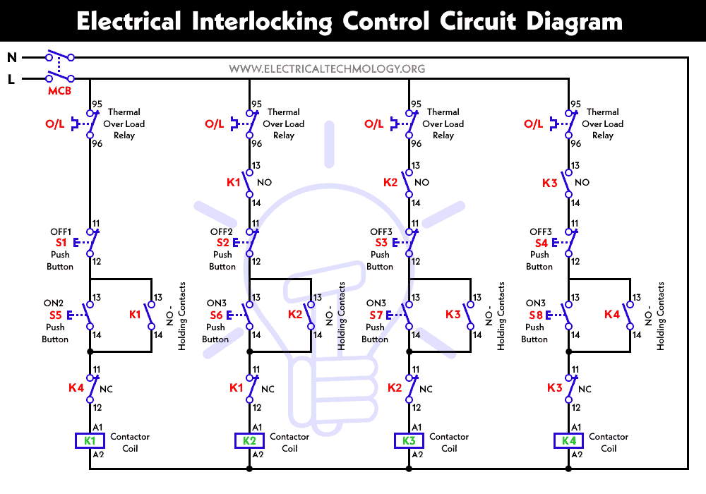
Each contact in a ladder diagram plc program represents the reading of a single bit in memory while each coil represents the writing of a single bit in memory. Contactors use 120 volt standard power to energize a magnetic coil which causes a set of internal contacts to close and provide higher power to the equipment. Selection by horsepower rating ac coil rated power hp per ac3 iec 60947 4 1 n a120 part numbers rated power hp per ul508 csa c222 i phase 3 phase i phase 3 phase auxilary contact ino inc ino inc part numbers ycln 5 ycln 5b ycin 6 ycinb coil. These voltages must be electrically isolated from the standard 120 volts ac. You will be in a position to understand exactly once the assignments ought to be completed that makes it much simpler to suit your needs to correctly manage. Coil voltage code n.
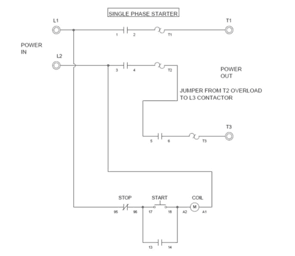
Control devices are connected between l1 and the operating coil. Compact contactorsopen type magnet coil suffix notes 1 rating per pole. Use these tips to learn how to wire a contactor. Operating coils of contactors and starters are activated by control devices such as pushbuttons limit switches and pressure switches. Electric motor controls g.


